Regulators / In-Line with Gauge (Part Numbers - CAD Download)
- Volume Discount
*When using with a soft tube, such as one made from urethane, use a tube ferrule insert to prevent the tube coming out.
Part Number
Once your search is narrowed to one product,
the corresponding part number is displayed here.
RGUNP6-4
- Drawing / Specifications
- 3D Preview 3D preview is available after complete configuration
- Part Numbers
- More Information
- Catalog

Specifications
| Part Number |
| RGUNP4 |
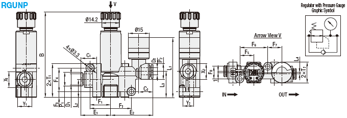
| Part Number | D1 | D2 | B | L1 | L2 | L3 | L4 | P1 | P2 | P3 | C1 | C2 | E1 | E2 | F1 | F2 | F3 | F4 | F5 | F6 | F7 | F8 | T1 | T2 | X1 | X2 | Y1 | Y2 | Mass (g) | Unit Price | Volume Discount Rate | ||
| Type | No. | Max | Min | 1 ~ 9 pc(s). | 10~30 | ||||||||||||||||||||||||||||
| RGUNP | 4 | 4 | 4 | 61.6 | 59 | 43.3 | 13 | 18.8 | 1 | 11.5 | 11.5 | 15 | 11 | 11 | 21.6 | 30.6 | 15 | 30 | 4.2 | 17 | 10.1 | 20.2 | 10.2 | 9 | 24.5 | 15 | 9.8 | 9.8 | 7.8 | 7.8 | 23 | ||
| 6-4 | 6 | 11.6 | 22 | 11.8 | 9.8 | 9.8 | |||||||||||||||||||||||||||
| 6 | 6 | 11.6 | 31 | 11.8 | 9.8 | ||||||||||||||||||||||||||||
| 8-6 | 8 | 65.7 | 63.1 | 49.8 | 15 | 22.5 | - | 15.5 | 15.5 | 19 | 18.1 | 17 | 28.6 | 33 | 19.9 | 39.7 | 4.1 | 21.3 | 11.6 | 23.2 | 9.1 | 13 | 28.4 | 19 | - | - | - | - | 36 | ||||
| 8 | 8 | 18.1 | 32.9 | ||||||||||||||||||||||||||||||
Part Number:
- In order to open the 3D preview, the part number must be fixed.
3D preview is not available, because the part number has not yet been determined.
Part Number
|
|---|
| RGUNP6-4 |
| Part Number |
Standard Unit Price
| Minimum order quantity | Volume Discount | Connection Dia. on Supply Side (D1) (mm) | Connection Dia. on Control Side (D2) (mm) | |
|---|---|---|---|---|---|---|
38.13 € | 1 | Available | 5 Days | 6 | 4 |
Loading...
More Information
Do not use the regulator in such a way that the pressure exceeds the preset level due to large pressure fluctuations on the secondary side.
This product is not designed as a relief valve, and using it as one may cause equipment damage or malfunction.
If using it in this way, please install additional safety mechanisms.
1. Set the pressure by turning the regulating knob in the upward direction (clockwise). The pressure cannot be set accurately if the regulating knob is turned in the downward direction (counterclockwise).
2. Do not turn the regulating knob counterclockwise from a fully open position, or too far clockwise from a fully open position.
Doing so may cause damage to the regulating knob or the regulator/valve itself. It can also increase the torque on the regulating screw and regulating knob.
3. The regulating knob releases when pulled up and locks when pushed down. Always lock the knob after adjusting the pressure. Failure to lock the regulating knob means the knob may turn, causing the pressure to change.
4. When you press down the regulating knob, it can sometimes stop partway between the locked and unlocked positions depending on how far round it is rotated. When this happens, the knob is not completely locked. Please ensure that the regulating knob is fully pushed down to the locked position.
5. Trying to force the regulating knob to turn while it is in the locked position may cause damage to the locking mechanism.
6. For models with a gauge, the gauge can be oriented in any direction. Applying excessive force to the gauge cap can result in damage to the gauge and cause issues with gauge readings. Please hold the gauge close to the base when turning it.
7. The pressure gauge is accurate to ±5% (FS). If greater accuracy is required, please check the pressure using a separate pressure gauge and adjust accordingly.
8. When air is released from the secondary side, the air flow may cause resonance. Avoid releasing air on the secondary side for prolonged periods of time, as this poses a risk of internal damage or other issues.
1. Adjusting the pressure
Release the lock by pulling the regulating knob upward before adjusting the pressure. Do not apply excessive force to the regulating knob during this time, as doing so may cause damage.

2. Increasing the pressure
Turn the regulating knob clockwise from the fully open position to increase the pressure. When the desired pressure is reached, be sure to push the regulating knob down to lock it in place so that the pressure setting does not change.
3. Decreasing the pressure
If the regulator knob is turned too far (if the pressure is too high), turning it counterclockwise will activate the relief mechanism and decrease the pressure. Following this, adjust as described in "2. Increasing the pressure." When the desired pressure is reached, be sure to push the regulating knob down to lock it in place so that the pressure setting does not change.

| Applicable Fluid | Air |
| Operating Temp. Range | 0 ~ 60°C |
| Operating Pressure Range | 0~1MPa |
| Set Pressure Range | 0.1~0.8MPa |
| (Indicated Pressure Range) | 0~0.8MPa |
| Gauge Accuracy | ±5% (Full Scale *) |
Basic information
| Type | Speed Controllers | Joint Type | Both Sides One-Touch Fitting | Usage Environment/Application | Standard |
|---|---|---|---|---|---|
| Operating Temperature Range(℃) | 0::60 | Operating Pressure Range(MPa) | 0::0.9 |
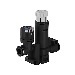
This page is Regulators / In-Line with Gauge, part number RGUNP6-4.
You can find the detail information about specifications and dimensions on part number RGUNP6-4.
- The specifications and dimensions of some parts may not be fully covered. For exact details, refer to manufacturer catalogs .
Variation of this product
| Part Number |
|---|
| RGUNP4 |
| RGUNP6 |
| RGUNP8 |
| RGUNP8-6 |
| Part Number | Standard Unit Price | Minimum order quantity | Volume Discount | Standard Shipping Days ? | Connection Dia. on Supply Side (D1) (mm) | Connection Dia. on Control Side (D2) (mm) |
|---|---|---|---|---|---|---|
40.66 € | 1 | Available | 5 Days | 4 | 4 | |
42.57 € | 1 | Available | 5 Days | 6 | 6 | |
43.83 € | 1 | Available | 5 Days | 8 | 8 | |
43.06 € | 1 | Available | 5 Days | 8 | 6 |
Complementary Products
Tech Support
- Technical Support
- Tel:+49 69 668173-0 / FAX:+49 69 668173-360
- Technical Inquiry


