Potvrzeno
- Compatible Wire Size(AWG)
- Core Wire Cross-sectional Area(mm2)
- Odhadované dodací dny
- Vše
- V rámci 5 pracovních dnů
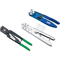
Crimping Tool for CE01 Crimp Contacts Only
Specifikace produktu
Specifications

| Model | Compatible Contact | Type | Compatible Wire | Weight g | |
| AWG Size | Core Wire Cross-sectional Area mm 2 | ||||
| 357J-12605-CE01 (*1) | CE01-#8P-C1M | Male Contact | 8 ~ 10 | 5.5 ~ 8.0 | 630 |
| CE01-#8S-C1M | Female Contact | ||||
| CE01-#8P-C2M | Male Contact | 10 ~ 12 | 3.5 ~ 5.5 | ||
| CE01-#8S-C2M | Female Contact | ||||
| 357J-12725-CE01 (*2) | CE01-#12P-C1M | Male Contact | 12 ~ 16 | 1.25 ~ 3.5 | 622 |
| CE01-#12S-C1M | Female Contact | ||||
| 357J-13426-CE01 | CE01-#16P-C1416 | Male Contact | 14 | 2.0 | 840 |
| CE01-#16S-C1416 | Female Contact | ||||
| 357J-13411-CE01 | CE01-#16P-C1620 | Male Contact | 16 ~ 20 | 0.5 ~ 1.25 | 840 |
| CE01-#16S-C1620 | Female Contact | ||||
| 357J-13412-CE01 | CE01-#16P-C2024 | Male Contact | 20 ~ 24 | 0.2 ~ 0.5 | 530 |
| CE01-#16S-C2024 | Female Contact | ||||
| 357J-13413-CE01 | CE01-#20P-C1 | Male Contact | 18 ~ 22 | 0.3 ~ 0.75 | 840 |
| CE01-#20P-C1 | Female Contact | ||||
| 357J-13414-CE01 | CE01-#20P-C2 | Male Contact | 22 ~ 26 | 0.15 ~ 0.3 | 530 |
| CE01-#20P-C2 | Female Contact | ||||
*2: 357J-12725-CE01 includes the tool body, locator and inspection gauge.
Podrobné údaje
Základní informace
Crimping tool for the CE01, a crimp connector with excellent environmental resistance, capable of connecting protective circuits according to JIS-B-6015, depending on contact size.

· Perform crimping with the dedicated crimping tools.
· Calibration requests are not accepted by our company.
Společné specifikace
Protection Circuit Connection Structural Diagram

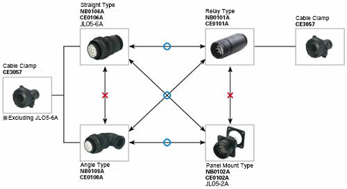
About Compatible Products
NB01 connectors, CE01 connectors, and JL05 connectors are compatible with each other.Combination Method

Material / Finish
| Item | Materials | Finish |
|---|---|---|
| Shell (Body) | Aluminum Alloy | Black Chromate Treatment |
| Insulator | Polyester Resin | UL94V-0, Gray |
| Contact | Copper Alloy | Silver Plating |
| O-ring | Nitrile Rubber | Black |
| Coupling Nut | Aluminum Alloy | Black Chromate Treatment |
| Earth Lug | Steel Alloy | Silver Plating |
| Rear Gasket for Flange | Chloroprene Rubber | Black |
Electrical and Mechanical Properties, Compatible Wires
| Item | Characteristics | |||||||
|---|---|---|---|---|---|---|---|---|
| Rated Current | Contact Size | #20 | #16 | #12 | #8 | |||
| Maximum Value per 1 Piece | 5 A | 13 A | 23 A | 46 A | ||||
| Rated Voltage | Rating Classification | AC (r.m.s) | DC | |||||
| INST | 200 | 250 | ||||||
| A | 500 | 700 | ||||||
| D | 900 | 1,250 | ||||||
| Withstand Voltage | INST | 1,000 VAC (r.m.s) 1 minute | ||||||
| A | 2,000 VAC (r.m.s) 1 minute | |||||||
| D | 2,800 VAC (r.m.s) 1 minute | |||||||
| Insulation Resistance | 5,000 MΩ or more at 500 VDC | |||||||
| Contact Resistance | Contact Size | #20 | #16 | #12 | #8 | |||
| mΩ or less | 8 | 4 | 2 | 0.6 | ||||
| Operating Temperature Range | -55°C ~ +125°C | |||||||
| Waterproofing | IP67 Equivalent | |||||||
| Humidity | Relative Humidity 95% or less | |||||||
| Service Life | 500 Insertions and Removals | |||||||
| NB01 (Solder Type) Compatible Wires (Note 2) |
Contact Size | #16 | #12 | #8 | ||||
| Conductor Cross-sectional Area | 0.75 mm2 or less | 3.5 mm2 or less | 8 mm2 or less | |||||
| AWG Size | 18 or less | 12 or less | 8 or less | |||||
(Note 1) Rated voltage and voltage resistance are shown with rating classification symbols (INST, A; D). Refer as well to the table below.
Contact Arrangement Diagram
| Number of Contacts | 4 | 5 | 7 | 7 | 8 |
|---|---|---|---|---|---|
| Arrangement No. | 22-22 | 18-11 | 20-15 | 24-10 | 22-23 |
| Contact Size | #8 | #12 | #12 | #8 | #12 |
| Contact Arrangement (Note 1) (Note 2) |
 |
 |
 |
 |
 |
| Rating Classification | A | A | A | A | D (4), A (Others) |
| Number of Contacts | 10 | 17 | 19 | 19 | 24 |
|---|---|---|---|---|---|
| Arrangement No. | 18-1 | 20-29 | 18-19A | 22-14 | 24-28 |
| Contact Size | #16 | #16 | #20 | #16 | #16 |
| Contact Arrangement (Note 1) (Note 2) |
 |
 |
 |
 |
 |
| Rating Classification | A (3, 5, 6, 8), INST (Others) |
A | INST | A | INST |
| Number of Contacts | 30 | 37 | 52 | 73 |
| Arrangement No. | 20-30A | 28-21 | 24-52A | 28-73A |
| Contact Size | #20 | #16 | #20 | #20 |
| Contact Arrangement (Note 1) (Note 2) |
 |
 |
 |
 |
| Rating Classification | INST | A | INST | INST |
|---|
(Note 1) View from the male (pin) connector coupling surface.
(Note 2) The ○ in the arrangement table shows the earth terminals (for protection of terminal connections).
Panel Cut Size Drawing

| Compatible Shell Size |
φA ±0.5 |
φB +0.2 -0 |
C ±0.13 |
Mounting Screws (Reference) | Rear Mounting Panel Thickness Limit |
|
|---|---|---|---|---|---|---|
| Inch Screws | Metric Screws | |||||
| 18 | 30.2 | 3.3 | 26.97 | #4-40 | M3 | 3.0 or less |
| 20 | 34.9 | 3.3 | 29.36 | #4-40 | M3 | |
| 22 | 36.6 | 3.3 | 31.75 | #4-40 | M3 | |
| 24 | 39.7 | 4.3 | 34.92 | #6-32 | M4 | |
| 28 | 46.1 | 4.3 | 39.67 | #6-32 | M4 | |
Číslo dílu bylo potvrzeno