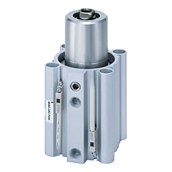
MK-Z Rotary Clamp Cylinder, Standard w / Auto Switch Mounting Grooves (MKB32-20LZ-M9N)
- Promotional pricing
- Volume Discount
Product Details:
Manufacturer part number: MKB32-20LZ-M9N
Brand: SMC
Price: 302.27 €
Delivery time: 26 Days
Technical Data:
Cylinder Diameter: 32 Ø
Stroke: 20 mm
Rod Tip Shape: Female Thread
Support Type: [Through Hole, Both Ends Tapped (Common)] Through Hole/Both Ends Tapped Commonly (Standard)
Body options: No (Standard)
(i)Remark
- Refer to the catalog for details on product specifications.
- The products shown in the image are representative. CAD data is not supported for some model numbers.
Part Number
Once your search is narrowed to one product,
the corresponding part number is displayed here.
MKB32-20LZ-M9N
Rotary Clamp Cylinder, Standard Type, MK Series Details

Rotary Clamp Cylinder, Standard Type, MK Series: product images
Rotary Clamp Cylinder, Standard Type, MK Series Specifications
| Bore size (mm) | 12 | 16 | 20 | 25 | 32 | 40 | 50 | 63 |
|---|---|---|---|---|---|---|---|---|
| Action | Double acting type | |||||||
| Rotary angle Note 1) | 90° ±10° | |||||||
| Rotary direction Note 2) | Left, right | |||||||
| Rotary stroke (mm) | 7.5 | 9.5 | 15 | 19 | ||||
| Clamp stroke (mm) | 10, 20, 30 | 10, 20, 30, 50 | ||||||
| Theoretical clamping force (N) Note 3) | 40 | 75 | 100 | 185 | 300 | 525 | 825 | 1,400 |
| Applicable fluids | Air | |||||||
| Proof pressure | 1.5 MPa | |||||||
| Operating pressure range | 0.1 to 1 MPa | 0.1 to 0.6 MPa Note 4) | ||||||
| Ambient and fluid temperature | Without auto switch: -10 to 70°C (no freezing) With auto switch: -10 to 60°C (no freezing) | |||||||
| Lubrication | Non-lube | |||||||
| Piping port size | M5 × 0.8 | Rc 1/8, NPT1/8 G1/8 | Rc1/4, NPT1/4 G1/4 | |||||
| Mounting | Through-hole / Both ends tapped common, head flange | |||||||
| Cushion | Rubber bumper | |||||||
| Stroke length tolerance | +0.6 -0.4 | |||||||
| Piston speed Note 5) | 50 to 200 mm/s | |||||||
| Non-rotating accuracy (clamp part) Note 1) | ±1.4° | ±1.2° | ±0.9° | ±0.7° | ||||
- *Note 1) Refer to the rotary angle diagram.
- *Note 2) Direction of rotation viewed from the rod end when the piston rod is retracted.
- *Note 3) Indicates the clamping force at a pressure of 0.5 MPa.
- *Note 4) When using within a pressure range from 0.61 to 1 MPa, use the -X2071.
- *Note 5) Be sure to connect a speed controller to the cylinder, and adjust the cylinder speed so that it is within the range of 50 to 200 mm/s. Make sure the valve is in the fully closed position and then gradually open the valve to adjust the speed of the speed controller.
Rotary angle diagram
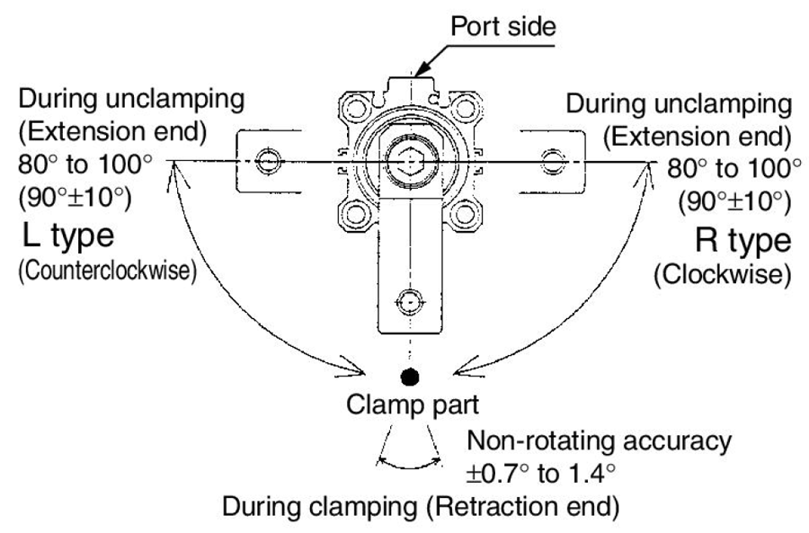
Rotary angle diagram
Model Number Notation
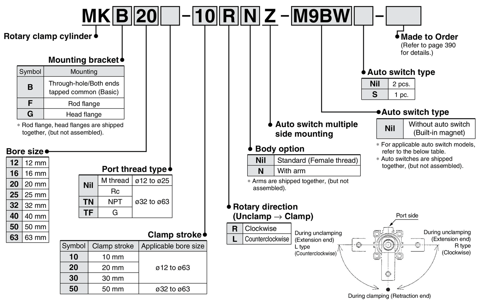
Model number example
Individual Made-to-Order Specifications
| Indicator symbol | Specifications/contents |
|---|---|
| -X2071 | Maximum operating pressure: 1.0 MPa specification |
| -X2094 | Overall length is the same as for the MK2 Series |
| -X2172 | Head side with spigot |
| -X2177 | Head flange dimensions are equivalent to the dimensions of the pre-existing MK, MK2 Series |
| -X2997 | Rotary angle: 60° specification |
Made to order specifications
| Indicator symbol | Specifications/contents |
|---|---|
| -XB6 | Heat-resistant cylinder (-10 to 150°C) without auto switch only Note 1) |
| -XC22 | Seal type: fluororubber Note 2) |
- *Note 1) Except ø12 (diameter 12 mm), ø16 (diameter 16 mm).
- *Note 2) The damper is a standard product.
Structural Drawings
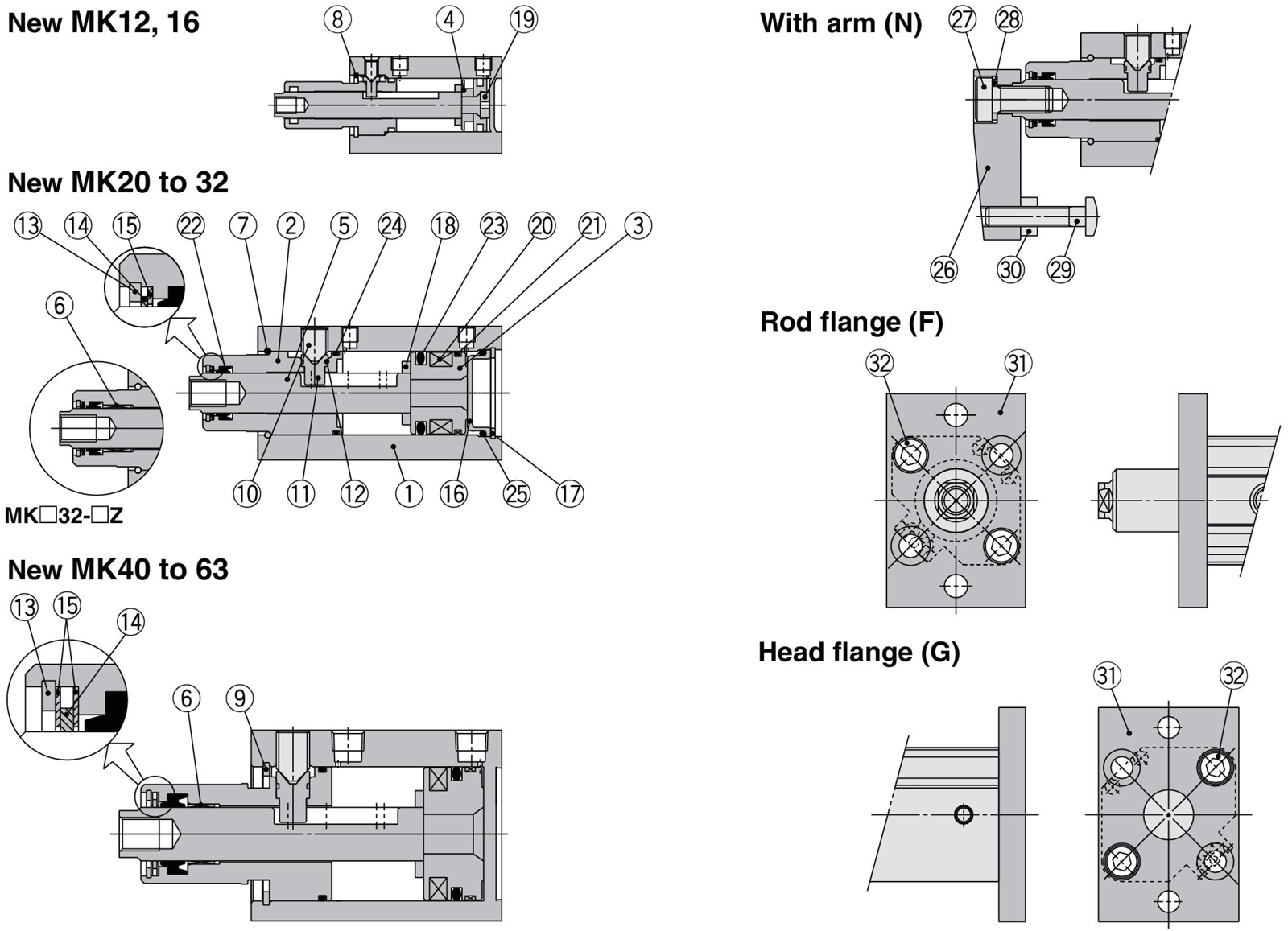
Rotary Clamp Cylinder, Standard Type, MK Series: structural drawings
Component Parts
| Number | Part name | Materials | Additional notes |
|---|---|---|---|
| 1 | Cylinder tube | Aluminum alloy | Hard anodized |
| 2 | Rod cover | Aluminum alloy | Hard anodized |
| 3 | Piston | Aluminum alloy | - |
| 4 | Magnet holder | Aluminum alloy | - |
| 5 | Piston rod | Stainless steel | ø12 to 25 (diameter 12 to 25 mm), nitriding |
| Carbon steel | ø32 to 63 (diameter 32 to 63 mm) heat treated, nickel plated | ||
| 6 | Bushing | Copper bearing material | Use only ø32 to 63 (diameter 32 to 63 mm) |
| 7 | Stop ring | Stainless steel | Use only ø20 to 32 (diameter 20 to 32 mm) |
| 8 | Round type R retaining ring | Carbon tool steel | Use only ø12 (diameter 12 mm), ø16 (diameter 16 mm) |
| 9 | Type C retaining ring | Carbon tool steel | Use only ø40 to 63 (diameter 40 to 63 mm) |
| 10 | Hex socket head set screw | Chrome molybdenum steel | Sharp end section 90° |
| 11 | Guide pin | Stainless steel | Nitriding |
| 12 | O-ring | NBR | - |
| 13 | Round type R retaining ring | Carbon tool steel | Except ø12 (diameter 12 mm), ø16 (diameter 16 mm) |
| 14 | Coil scraper | Phosphor bronze | Except ø12 (diameter 12 mm), ø16 (diameter 16 mm) |
| 15 | Scraper presser | Stainless steel | Except ø12 (diameter 12 mm), ø16 (diameter 16 mm) |
| 16 | Head cover | Rolled steel | Electroless nickel plated |
| 17 | Type C retaining ring | Carbon tool steel | Use only ø20 to 32 (diameter 20 to 32 mm) |
Component Parts
| Number | Part name | Materials | Additional notes | |
|---|---|---|---|---|
| 18 | Bumper | Urethane | - | |
| 19 | Bumper B | Urethane | Use only ø12 (diameter 12 mm), ø16 (diameter 16 mm) | |
| 20 | Magnet | - | - | |
| 21 | Wear ring | Resin | Except ø12 (diameter 12 mm), ø16 (diameter 16 mm) | |
| 22 | Rod seal | NBR | - | |
| 23 | Piston seal | NBR | - | |
| 24 | Gasket | NBR | - | |
| 25 | O-ring | NBR | Use only ø20 to 32 (diameter 20 to 32 mm) | |
| 26 | Arm | Rolled steel | - | |
| 27 | Hex socket head cap screw | Chrome molybdenum steel | - | |
| 28 | Spring washer | Hard steel | - | |
| 29 | Clamp bolt | Chrome molybdenum steel | - | |
| 30 | Hex nut | Rolled steel | - | |
| 31 | Flange | Rolled steel | Rod flange is not compatible with the head flange | |
| 32 | Hex socket head cap screw | Chrome molybdenum steel | Quantity | ø12 (diameter 12 mm), ø16 (diameter 16 mm), ø32 to 40 (diameter 32 to 40 mm): 4 pcs. |
| ø20 (diameter 20 mm), ø25 (diameter 25 mm): 2 pcs. | ||||
Replacement Parts / Seal Kit
| Bore size (mm) | ø12 (diameter 12 mm) | ø16 (diameter 16 mm) | ø20 (diameter 20 mm) | ø25 (diameter 25 mm) | ø32 (diameter 32 mm) | ø40 (diameter 40 mm) | ø50 (diameter 50 mm) | ø63 (diameter 63 mm) |
|---|---|---|---|---|---|---|---|---|
| Order number | CQSB12-PS | CQSB16-PS | MK20Z-PS | MK25Z-PS | MK32Z-PS | MK2T40-PS | MK2T50-PS | MK63Z-PS |
| Contents | Set of above numbers (22), (23), (24) | Set of above numbers (14), (22), (23), (24) | ||||||
- *The seal kit is 1 set of the numbers indicated in the table. Order the seal kit based on the order numbers for each tube bore size.
- *The seal kit does not include a grease pack, so please order a grease pack separately. Grease pack part number: GR-S-010 (10 g)
Replacement Parts / Guide Pin Kit
| Bore size (mm) | ø12 (diameter 12 mm) | ø16 (diameter 16 mm) | ø20 (diameter 20 mm) | ø25 (diameter 25 mm) | ø32 (diameter 32 mm) | ø40 (diameter 40 mm) | ø50 (diameter 50 mm) | ø63 (diameter 63 mm) |
|---|---|---|---|---|---|---|---|---|
| Order number | MK12Z-GS | MK16Z-GS | MK20Z-GS | MK25Z-GS | MK32Z-GS | MK40Z-GS | MK50Z-GS | MK63Z-GS |
| Contents | A set of (10), (11), (12) listed above | |||||||
- *The guide pin kit is 1 set of the numbers indicated in the table. Order the seal kit based on the order numbers for each tube bore size.
- *Refer to the manufacturer's operating manual for the replacement procedure for the replacement parts and seal and guide pin kits.
Rotary Clamp Cylinder, Standard Type, MK Series Dimensions
(Unit: mm)
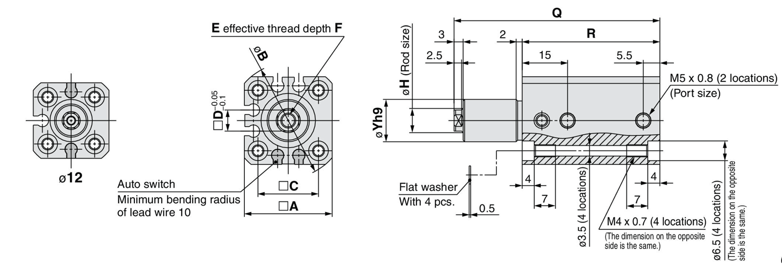
Through hole / Both ends tapped common (basic type): dimensional drawing
| Model | A | B | C | D | E | F | H | øYh9 |
|---|---|---|---|---|---|---|---|---|
| MKB12-Z | 25 | 32 | 15.5 | 5 | M3 × 0.5 | 5.5 | 6 | 11 (-0.043 to 0) |
| MKB16-Z | 29 | 38 | 20 | 7 | M5 × 0.8 | 6.5 | 8 | 14 (-0.043 to 0) |
| Model | Rod state | Clamp stroke | |||||
|---|---|---|---|---|---|---|---|
| 10 mm | 20 mm | 30 mm | |||||
| Q | R | Q | R | Q | R | ||
| MKB12-Z | Retracted | 68 | 45.5 | 88 | 55.5 | 108 | 65.5 |
| Extended | 85.5 | 115.5 | 145.5 | ||||
| MKB16-Z | Retracted | 68 | 45.5 | 88 | 55.5 | 108 | 65.5 |
| Extended | 85.5 | 115.5 | 145.5 | ||||
- *Note) The above figure is with the auto switch D-M9□ mounted.
Part Number
|
|---|
| MKB32-20LZ-M9N |
| Part Number |
Standard Unit Price
| Minimum order quantity | Volume Discount | Cylinder Diameter (Ø) | Stroke (mm) | Rod Tip Shape | Support Type | Body options | Max. Pressure (MPa) | Clamping Force (kN) | Rotating Direction | Auto Switch | Lead Wire Length (m) | Number of Switches | Port Screw Type | Made to order specifications | |
|---|---|---|---|---|---|---|---|---|---|---|---|---|---|---|---|---|---|
302.27 € | 1 | 26 Days | 32 | 20 | Female Thread | [Through Hole, Both Ends Tapped (Common)] Through Hole/Both Ends Tapped Commonly (Standard) | No (Standard) | 1 | 0.3 | Left Hand | M9N | 0.5 | 2 | Rc | None |
Loading...
Basic information
| Operation Method | Move Turning | Rod Motion | Double Acting Piece Rod | Rotation Angle θ | 90°±10° |
|---|---|---|---|---|---|
| Specifications | Built-in magnet | Mounting surface position | Multi-face mounting |
Configure
Basic Attributes
-
Type
- MK
- MKB
-
Cylinder Diameter(Ø)
-
Stroke(mm)
-
Rod Tip Shape
- Female Thread
- Others
-
Support Type
- Rod Side Flange
- Head side flange
- Through Hole, Both Ends Tapped (Common)
-
Body options
- No (Standard)
- With Arm
-
Max. Pressure(MPa)
-
Clamping Force(kN)
-
Rotating Direction
- Right
- Left Hand
-
Auto Switch
-
Lead Wire Length(m)
- 0.5
- 0.5 (SC type)
- 0.5 (M8 3-pin plug connector)
- 0.5 (M12 4-pin A-cord [normal-key] plug connector)
- 1
- 1 (M8 3-pin plug connector)
- 1 (M8 4-pin plug connector)
- 3
- 5
-
Number of Switches
-
Port Screw Type
- G
- M thread
- NPT
- Rc
-
Made to order specifications
- Heat-resistant cylinder (-10 to 150°C) without auto switch only
- Maximum operating pressure 1.0 MPa specification
- Head flange dimensions are equivalent to the dimensions of the pre-existing MK, MK2 series
- Overall length is the same as for the MK2 Series
- Fluoroelastomer seal
- Head side with spigot
- None
-
Filter by CAD data type
- 2D
- 3D
Filter by standard shipping days
-
- All
- Same day
- 3 Days or Less
- 4 Days or Less
- 6 Days or Less
- 7 Days or Less
- 22 Days or Less
- 26 Days or Less
- 31 Days or Less
- 98 Days or Less
Optional Attributes
- The specifications and dimensions of some parts may not be fully covered. For exact details, refer to manufacturer catalogs .
Tech Support
- Technical Support
- Tel:+49 69 668173-0 / FAX:+49 69 668173-360
- Technical Inquiry
