
- inCAD Library Home
- > No.000222 Stepped Feed Mechanism Using Cylinder
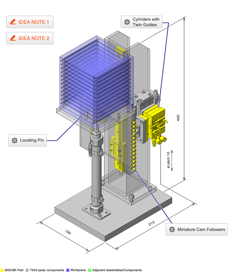
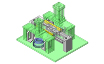
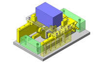
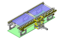
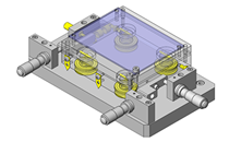
No.000222 Stepped Feed Mechanism Using Cylinder
36
Cylinder-driven stepped feed
Related Category


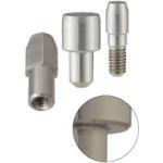
Miniature Cam Followers
| Product name | Miniature Cam Followers |
|---|---|
| Part number | CFFAM3-6 |
Selection criteria
Create even intervals for height adjustment of workpiece supporting plate.
Available sizes
■Miniature Cam Followers (General)
| Material |
|---|
| EN 1.3505 Equiv.(Stud: EN 1.7242 Equiv.) |
| EN 1.4125 Equiv. |
■Sizes and Dimensions
| Shaft Dia. (mm) | Outer Ring Dia. (mm) |
|---|---|
| 2.5 | 5 |
| 3 | 6 |
| 4 | 8 |
| 5 | 10 |
| 6 | 12 |
Accuracy Info
■Cam follower accuracy
| Shaft Dia. (mm) | Shaft Dia. Tolerance (mm) |
|---|---|
| 2.5 | 0 -0.006 |
| 3 | |
| 4 | 0 -0.008 |
| 5 | |
| 6 |
Performance info.
■Speeds / Loads (Load Info) of the Cam Followers
| Shaft Dia. (mm) | Basic Load Rating | Max. allowable load (N) | Rotational speed limit (rpm) | |
|---|---|---|---|---|
| Basic dynamic load rating (N) | Basic staic load rating(N) | |||
| 2.5 | 350 | 285 | 285 | 3360 |
| 3 | 565 | 525 | 525 | 2800 |
| 4 | 915 | 915 | 915 | 2100 |
| 5 | 1340 | 1400 | 1400 | 1680 |
| 6 | 1880 | 2040 | 2040 | 1400 |

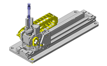
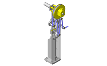
Cylinders with Twin Guides
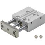
| Product name | Cylinders with Twin Guides |
|---|---|
| Part number | MGCLB12-10 |
| Features | Cylinder uses two rods and bushings for guidance and rigidity. |
Selection criteria
Design and stroke, since cylinders are used to press against cam followers.
Available sizes
■Cylinder with guides (Fix stroke type)
| Cyl. Bore | Bearing | Plain Bushing | Linear Ball Bushing | Cylinder width (mm) | Overall Length (Listed below + St) | Thickness (mm) | ||||||||||||||
|---|---|---|---|---|---|---|---|---|---|---|---|---|---|---|---|---|---|---|---|---|
| St | 10 | 20 | 25 | 30 | 40 | 50 | 75 | 100 | 10 | 20 | 25 | 30 | 40 | 50 | 75 | 100 | ||||
| Ø12 | ○ | ○ | - | ○ | ○ | ○ | ○ | ○ | ○ | ○ | - | ○ | ○ | ○ | ○ | ○ | 56 | 39 | 22 | |
| Ø16 | ○ | ○ | - | ○ | ○ | ○ | ○ | ○ | ○ | ○ | - | ○ | ○ | ○ | ○ | ○ | 62 | 43 | 25 | |
| Ø20 | - | ○ | - | ○ | ○ | ○ | ○ | ○ | ○ | ○ | - | ○ | ○ | ○ | ○ | ○ | 72 | 47 | 30 | |
| Ø25 | - | ○ | - | ○ | ○ | ○ | ○ | ○ | - | ○ | - | ○ | ○ | ○ | ○ | ○ | 86 | 47.5 | 38 | |
| Ø32 | - | - | ○ | - | - | ○ | ○ | ○ | - | - | ○ | - | - | ○ | ○ | ○ | 112 | 48 | ||
| Ø50 | - | - | ○ | - | - | ○ | - | ○ | - | - | - | - | - | - | - | - | 146 | 72 | 60 | |
Selection steps
■Cylinder Selection Steps
1. Define various conditions of the load.
↓
2. Calculate cylinder output (In case of double acting type)
↓
3. Determine the cylinder bore
↓
4. Determine the theoretical reference speed.
↓
5. Verify the cylinder's cushion mechanism.
↓
6. Verify the lateral load applied to the cylinder.
Accuracy Info
■Non-Rotational Accuracy
Non-Rotational Accuracy: A deviation angle centered on the piston rod, expressing the backlash caused by the clearance between the guide rod and the bearing.
| Cyl. Bore | Non-rotating Accuracy of Link Bar Tip | |
|---|---|---|
| Plain Bushing | Linear Bushing | |
| Ø12 | ±0.12° | ±0.06° |
| Ø16 | ±0.10° | ±0.06° |
| Ø20 | ±0.09° | ±0.05° |
| Ø25 | ±0.08° | ±0.05° |
| Ø32 | ±0.06° | ±0.04° |
| Ø50 | ±0.05° | - |
Performance info.
■Guided cylinder usage pressure range
Min. pressure(MPa): 0.1
Max. pressure(MPa): 1.0
Proof pressure(MPa): 1.5
(N)
| Cyl. Bore (mm) | Operating Direction | Operating Pressure (MPa) | |
|---|---|---|---|
| 0.4 | 0.5 | ||
| 12 | Outstroke | 45 | 57 |
| Instroke | 34 | 42 | |
| 16 | Outstroke | 80 | 101 |
| Instroke | 60 | 75 | |
| 20 | Outstroke | 126 | 157 |
| Instroke | 94 | 118 | |
| 25 | Outstroke | 196 | 245 |
| Instroke | 151 | 189 | |
| 32 | Outstroke | 322 | 402 |
| Instroke | 241 | 302 | |
| 50 | Outstroke | 785 | 982 |
| Instroke | 660 | 825 | |
■Allowable Lateral Load
(N・m)
| Cyl. Bore (mm) | Stroke (mm) | |||||||
|---|---|---|---|---|---|---|---|---|
| 10 | 20 | 25 | 30 | 40 | 50 | 75 | 100 | |
| 12 | 24 | 19 | 16 | 14 | 12 | 37 | 31 | |
| 16 | 40 | 33 | 28 | 24 | 21 | 55 | 46 | |
| 20 | 52 | 45 | 39 | 35 | 55 | 46 | ||
| 25 | 69 | 60 | 52 | 47 | 73 | 62 | ||
| 32 | 166 | 131 | 107 | 91 | ||||
| 50 | 296 | 245 | 241 | |||||

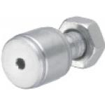
Locating Pin
| Product name | Large Head Tapered High Hardness Stainless Steel/Press Fit/ Tapped/ Threaded |
|---|---|
| Part number | AFPBA5-P6-L10-B6 |
Selection criteria
Effective for using as the workpiece positioning pin
Available sizes
■Locating Pins - High Rigidity Stainless Steel, Large Head, Tapered
| Material | Hardness | Pin Shape | Shank Shape | |||
|---|---|---|---|---|---|---|
| High Rigidity Stainless Steel | Hardness: 35HRC ~ | Round | Press Fitm 6 | Press Fitp 6 | Tapped g6 | Threaded g6 |
| Diamond | ||||||
■Sizes and Dimensions of the Press-fit Type
| Shank Dia. | Pin Head Dia. 0.01 mm Increments | Shank Pilot Length Unit: 1 mm Increments | Pin Section Length Unit: 0.1 mm Increments |
|---|---|---|---|
| Ø2 | 2.50 ~ 8.00 | 3(4) ~ 16 | 1.0 ~ 15.0 |
| Ø3 | 3.50 ~ 8.00 | ||
| Ø4 | 4.50 ~ 8.00 | ||
| Ø5 | 5.50 ~ 8.00 | ||
| Ø6 | 6.50 ~ 10.00 | ||
| Ø8 | 8.50 ~ 10.00 | 4(5) ~ 16 |
The dimension in ( ) is applicable to Diamond Shape.
■Sizes and Dimensions of the Tapped Type
| Shank Dia. | Pin Head Dia. 0.01 mm Increments | Shank Pilot Length Unit: 1 mm Increments | Pin Section Length Unit: 0.1 mm Increments |
|---|---|---|---|
| Ø6 | 6.50 ~ 10.00 | 6(9) ~ 16 | 1.0 ~ 15.0 |
| Ø8 | 8.50 ~ 10.00 | 8(12) ~ 16 |
The dimension in ( ) is applicable to Diamond Shape.
■Sizes and Dimensions of the Threaded Type
| Shank Dia. | Pin Head Dia. 0.01 mm Increments | Shank Pilot Length Unit: 1 mm Increments | Pin Section Length Unit: 0.1 mm Increments |
|---|---|---|---|
| Ø3 | 3.50 ~ 8.00 | 3 ~ 10 | 1.0 ~ 15.0 |
| Ø4 | 4.50 ~ 8.00 | ||
| Ø5 | 5.50 ~ 8.00 | ||
| Ø6 | 6.50 ~ 10.00 | ||
| Ø8 | 8.50 ~ 10.00 | 4 ~ 10 |
Accuracy Info
■Accuracy of the Locating Pins - High Rigidity Stainless Steel, Large Head, Tapered
| Press Fit | Threaded | Tapped | ||
|---|---|---|---|---|
| Shank Dia. Tolerance | m6 | g6 | g6 | g6 |
Pin Head Dia. Tolerance: 0/-0.01
Concentricity of the Shank Pilot and the Pin Head: Ø 0.01

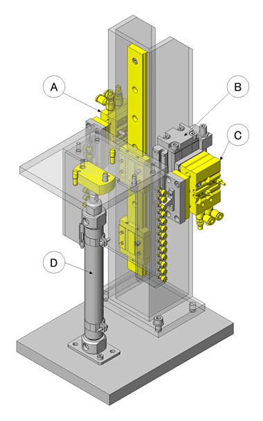
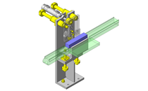
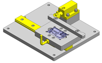
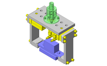
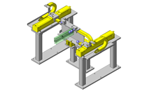
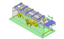
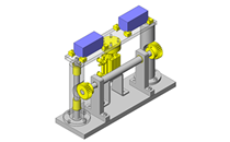
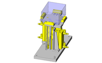
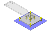
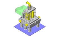
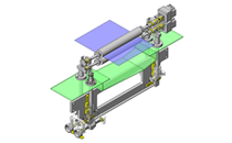
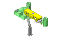
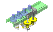
IDEA NOTE Stepped feed achieved only by air cylinder
By combining the movements of four air cylinders - A: stopper pin cylinder, B: pitch feed cylinder, C: feed pin cylinder, D: return cylinder (balancer cylinder), stepped feed is performed.


-

-
 Terms of use of CAD data and simplified drawing data
- These terms and conditions (hereinafter referred to as “the Terms") set forth the conditions for downloading CAD data and simplified drawing data provided by MISUMI Corporation (hereinafter referred to as "MISUMI") via www.misumi-europe.com operated by MISUMI Europa GmbH(hereinafter referred to as the "Website"). By downloading CAD data and simplified drawing data posted on the Website (hereafter referred to as “Data”), customers are deemed to have agreed to these Terms.
- 1. Purpose of Use
-
MISUMI offers the following:
1)CAD data found on the Website (3D CAD data, 3D Intermediate data and 2D CAD data) for the purpose of informing customers of the characteristics of the products offered by MISUMI or a manufacturer affiliated with MISUMI for use in their designs.
2)Simplified drawing data (in PDF format) for the purpose of checking the specifications of products. - 2. Characteristics of Data
- There may be a discrepancy in certain characteristics of products (for example: tolerance, surface roughness, chamfer, etc.) between the Data and the actual product. Furthermore, for the purpose of reducing the file size of the Data, some information such as oil groove shapes, threads, or spring shapes, may be removed from the Data.
- 3. Disclaimer
- MISUMI carefully creates the Data but makes no warranty as to the quality, accuracy, functionality, safety, reliability, etc., of the Data. MISUMI may at any time, and with no prior notice to customers, revise or delete Data. MISUMI assumes no responsibility for any damage or loss resulting from any revision or deletion of the Data, or any errors in said data. Customers are solely responsible for all aspects of their own designs, including those made using the Data. MISUMI may provide customers with design example data on the Website, but the quality, accuracy, functionality, safety, reliability, etc., of such data are not guaranteed. MISUMI may, at any time, and in its sole discretion, request that the customer cease its use of or destroy the Data in its possession. MISUMI may request the customer provide MISUMI documentation of such destruction.
- 4.Prohibited Acts
-
Customers or users of the Data, are prohibited from the following acts regarding the Data, in whole or in part:
(1)Requesting quotations or placing orders for products with third parties other than those authorized by MISUMI or its affiliates;
(2)Receiving quotations or orders for products from third parties by providing the Data to a third party or using the Data in their own business;
(3)Displaying links to the Website related to the Data on their own websites, etc., without consent of MISUMI or its affiliates;
(4)Using or reproducing the Data beyond the scope of the above-stated Purpose of Use;
(5)Modifying, altering, tampering with, translating, or adapting the Data;
(6)Selling, transferring, lending, sublicensing, or providing the Data to third parties in any way without consent of MISUMI or its affiliates;
(7)Altering the content, reverse engineering, decompiling, disassembling, or analyzing the Data;
(8)Publicly disclosing or exhibiting the Data without consent of MISUMI or its affiliates;
(9)Using the Data for the purpose of providing products and services identical or similar to those of MISUMI or its affiliates;
(10)Performing acts that interfere with the proper functioning of this Website, such as acquiring Data in bulk. - 5. Copyright
-
All title and copyright in and to any information contained in the Data are owned by MISUMI or the relevant manufacturer affiliated with MISUMI and are protected by applicable copyright laws and international treaties. By downloading Data, the customer acquires no ownership rights of any kind in the intellectual property contained within. Without prior approval from MISUMI, no part of the Data may be utilized (reproduced, modified, reverse-engineered, uploaded, presented, sent, distributed, licensed, sold, or published) for any purpose other than that mentioned above.
In the event Data is found to have been to be used for any purpose other than that mentioned above or against any applicable laws or the Terms, MISUMI may pursue any legal remedy available to it, which may result in forbidding the offending user from using the Data or accessing the Website. - 6. Third-Party Data
- MISUMI offers some Data provided by third parties. Such Data may be subject to separate terms and conditions, in addition to these terms. MISUMI makes no guarantee or warranty regarding Data from third parties.
- 7. Export Control
- Customers shall comply with all applicable laws and regulations regarding the export of the Data.
- 8. Amendments to the Terms
- MISUMI may, at any time, and in its sole discretion, modify these terms and conditions; any such modification will be effective immediately.
- 9. Severability
- If any term or provision of these Terms is invalid, illegal, or unenforceable in any jurisdiction, such invalidity, illegality, or unenforceability shall not affect any other term or provision of these Terms or invalidate or render unenforceable such term or provision in any other jurisdiction. Section 139 BGB (German Civil Code) shall not apply.
- 10.Miscellaneous
-
In the event that Customers violate the Terms, MISUMI and/or MISUMI Europa GmbH shall be entitled to claim the damages and expenses (including attorney's fees) incurred by such violation against the Customers.
These Terms and any disputes arising in connection therewith shall be exclusively governed by and construed in accordance with the laws of the Federal Republic of Germany, without regard to its conflicts of law principles. The courts located in Frankfurt am Main/Germany shall have exclusive jurisdiction to adjudicate any dispute arising in connection with these Terms. By downloading the Data, you agree to submit to the exclusive and personal jurisdiction of the courts located in Frankfurt am Main/Germany. - Revised: September 21, 2025
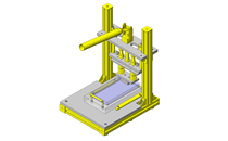
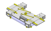
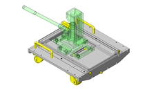
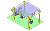
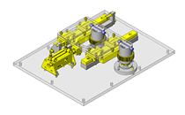
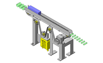
CAD Data Download (Unit Assembly)
CAD Data Download: File Format
Cautions on the CAD data
-
Assembly data shows the assembly drawings in the concept design phase. The sole purpose of the data is to explain the structure and functionality of the assembly and is not considered nor to be used as a final design.
You will need to edit the Data so that it meets your specific design conditions. -
The CAD data unit assembly consists of sub-assemblies.
Each sub-assembly unit can be used as it is or can be edited. - The Data for fabricated parts is based on easy-to-edit dimensions and shapes in sketches and histories.
- The Data including the third-part components are made by the Company.
* The part in the frame is a sub-assembly unit.
-

- * Unit assembly CAD data consists of some sub-assemblies.
Each sub-assembly unit can be used as it is or can be edited.
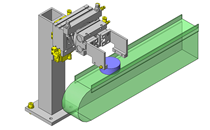
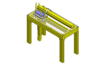
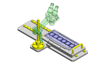
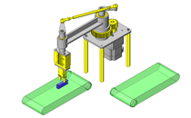
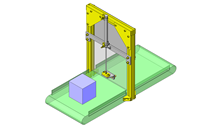
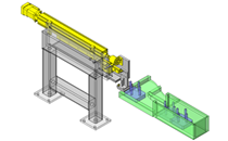
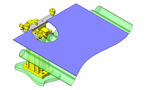
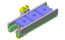
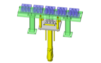
Application Overview
Purpose
- Purpose
- Performing pitch feed to a position for loading and unloading the workpiece stocker.
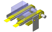
- Operation
- (1) Balancer cylinder descends to lower end, pitch feed cylinder descends, while stopper and feed pin cylinders are in retracted position.
(2) Stopper pin cylinder extends.
(3) Feed pin extends while stopper pin cylinder returns.
(4) Pitch feed cylinder ascends.
(5) Stopper pin extends and feed pin cylinder returns.
(6) Pitch feed cylinder descends, repeats (3) to (6) 12 times. (workpiece loading onto stacker)
(7) The balancer cylinder is at the upper end.
(8) Stopper pin returns.
(9) Returns to balancer cylinder lower end (unloading from stocker) (2).
* For the roles of the cylinders, refer to IDEA NOTE 1.
- (1) Balancer cylinder descends to lower end, pitch feed cylinder descends, while stopper and feed pin cylinders are in retracted position.
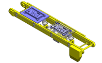
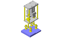
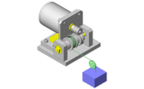
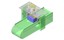
Target workpiece
- Shape: thin plate workpiece
- Size: W100 x D100 x t2.0 mm
- Weight: 0.03 kg
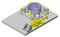
- Stocker (capable of mounting 12 thin plate workpieces)
- Size: W110 x D110 x H134 mm
Weight: 0.6 kg
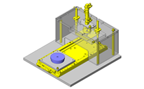
Design Specifications
Operating Conditions or Design Requirements
- Ascending feed pitch: 10 mm
- Outer dimensions: W150 x D210 x H400 mm
Selection Criteria for Main Components
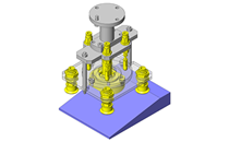
- Cam followers are used for position, retention/feed of the stacker. They are arranged at the same pitch as the stacker pitch.
- Select pitch feed cylinder to have same stroke as the stacker pitch.
- For the cylinders for stopper and push pin movement, select a stroke that allows the pin to escape.
Design Evaluation
Verification of main components
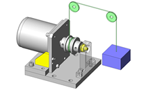
- Whether the selected cylinder is appropriate for the workpiece load is verified.
- Vertical feed Cylinder
- Conditional value: operating air pressure 0.5 (MPa), efficiency: 0.8
- Vertical feed cylinder thrust: 113 N
- Vertical feed cylinder thrust = cylinder thrust x efficiency = 113 x 0.8 = 90.4 N
Balancer Cylinder - Conditional value: operating air pressure 0.1 (MPa), efficiency: 0.8
- Cylinder theoretical thrust: 31 N
- Balancer cylinder thrust = cylinder thrust x efficiency = 31 x 0.8 = 24.8 N
Load factor - Conditional value: workpiece weight 0.03 (kg), stacker weight 0.6 (kg), weight of parts included in lift unit 1.8 (kg), number of workpieces 12
- From load = (workpiece weight + stacker weight + lift unit weight) x 9.8,
Load = (0.03 (kg) x 12 + 0.6 (kg) + 1.8 (kg)) x 9.8 = 27 N - From load factor (%) = (load/cylinder thrust) x 100,
Load factor = (27/ (90.4 + 24.8)) x 100 = 23.4(%) < 50 (%)
⇒Selected cylinder meet design requirements.
Other Design Consideration
- The balance cylinder of this mechanism is structured with an air regulator to prevent load from being applied to the stepped feed cylinder.
- By utilizing a cylinder with a stopper (an external stopper can also be used) as the vertical feed cylinder, fine adjustment is possible and a repeatability of ±0.05 mm is achieved.
Explore Similar Application Examples


Payment Method


On-Demand Manufacturing
Certificates


Copyright © MISUMI Corporation All Rights Reserved.