
- inCAD Library Home
- > No.000111 Z-axis elevating mechanism
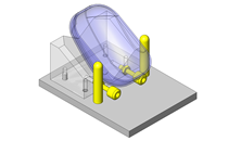
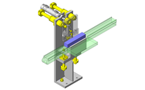
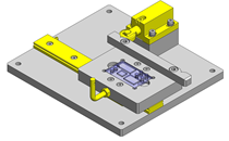
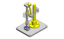
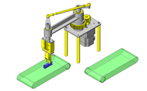
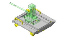
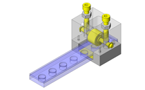
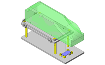
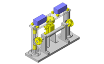
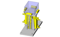
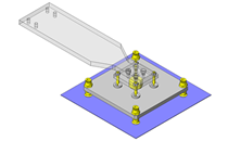
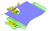
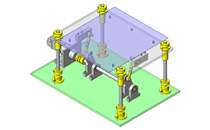
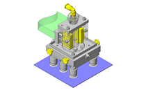
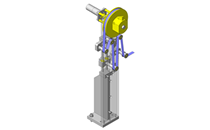
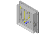
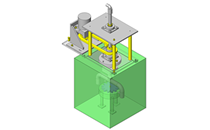
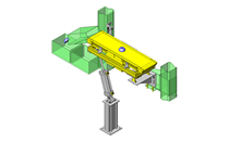
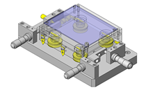
No.000111 Z-axis elevating mechanism
117
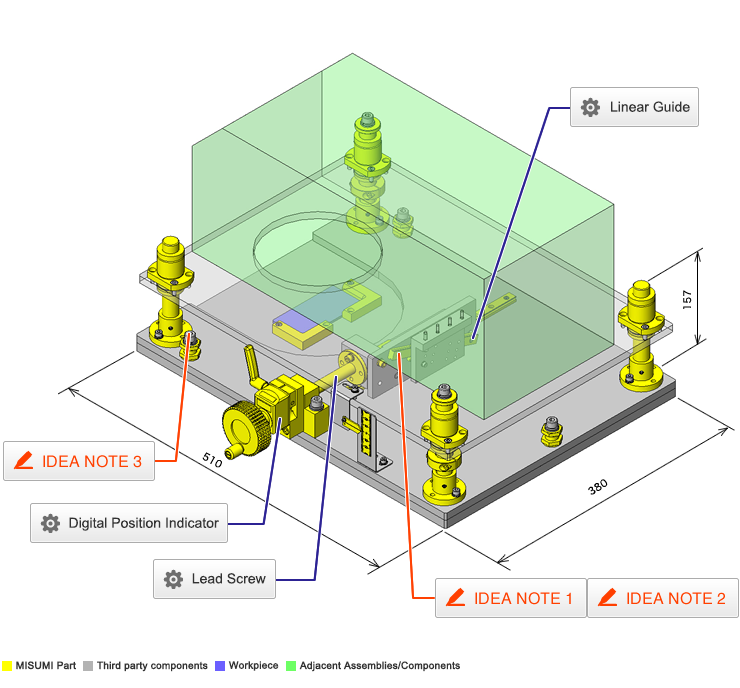
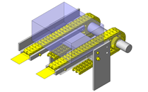
An elevating mechanism with slant mounted linear guide
Related Category


Linear Guide
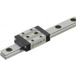
| Product name | Miniature Linear Guides/Standard Block with Dowel Holes |
|---|---|
| Part number | SSE2BNZ13-145 |
| Features | Dowel Hole facilitates positioning of Parts Mounted on Blocks |
Selection criteria
Effective as a linear motion system to move the table up / down by diagonally mounting.
Available sizes
■Miniature linear guide (Standard block with dowel holes, Slight clearance, Standard grade)
| Material | Hardness |
|---|---|
| EN 1.4125 Equiv. | 56HRC - |
| Carbon steel | 58HRC - |
■Sizes and Dimensions
| Number of blocks | Block | Overall height | Rail length | Dowel hole | ||
|---|---|---|---|---|---|---|
| Width | Length | DIA. | Depth | |||
| 1 | 17 | 23.6 | 8 | 40 - 130 | Ø3 | 2 |
| 20 | 30 | 10 | 35 - 275 | 2.5 | ||
| 27 | 33.9 | 13 | 45 - 470 | 3 | ||
| 32 | 42.4 | 16 | 70 - 670 | 4 | ||
| 40 | 50 | 20 | 100 - 700 | 4 | ||
| 2 | 17 | 23.6 x 2pcs. | 8 | 70 - 130 | 2 | |
| 20 | 30 x 2pcs. | 10 | 95 - 275 | 2.5 | ||
| 27 | 33.9 x 2pcs. | 13 | 120 - 470 | 3 | ||
| 32 | 42.4 x 2pcs. | 16 | 150 - 670 | 4 | ||
| 40 | 50 x 2pcs. | 20 | 160 - 700 | 4 | ||
* Please see the product pages for details of selectable sizes.
Selection steps
■Miniature linear guide selection steps
- Determine application conditions
- (Moving mass, feed rate, motion pattern, life)
↓
- Temporary selection of linear guide specifications
- (Block type, overall height, rail length are
temporarily selected.)
↓
- Confirm of basic safety
-
- ●Allowable load
- ●Life
- ●Preload
Accuracy Info
■Preload and accuracy standards (Standard block with dowel holes, Slight clearance, Standard grade)

(µm)
| Radial clearance | 0 ~ +15 |
|---|---|
| Tolerance of dims. H | ±20 |
| Pair variation of H | 40 |
| Tolerance of dims. W2 | ±25 |
| Pair variation of W2 | 40 |
(µm)
| Rail length (mm) | |||||||
|---|---|---|---|---|---|---|---|
| - 80 | 81 - 200 | 201 - 250 | 251 - 400 | 401 - 500 | 501 - 630 | 631 - 700 | |
| Running parallelism | 13 | 15 | 17 | 18 | 19 | 21 | 21.5 |
Performance info.
■Load capacity of linear guide (Standard block with dowel holes, Slight clearance, Standard grade)
| Overall height | Basic load rating | Allowable static moment | |||
|---|---|---|---|---|---|
| C (Dynamic) kN | Co (Static) kN | MA N・m | MB N・m | Mc N・m | |
| 8 | 0.9 | 1.5 | 4.1 | 4.1 | 5.2 |
| 10 | 1.5 | 2.5 | 5.1 | 5.1 | 10.2 |
| 13 | 2.2 | 3.3 | 8.8 | 9.5 | 16.1 |
| 16 | 3.6 | 5.4 | 21.6 | 23.4 | 39.6 |
| 20 | 5.2 | 8.5 | 48.4 | 48.4 | 86.4 |
Technical calculations
■Linear guide life calculations
- ●Life
- When the linear system is in motion with applied load, the rolling surfaces and races are subject to repeated stress. This stress can cause scale-like flaking due to material fatigue. The total run distance until the flaking appears is the "Life" of the linear system.
- ●Rated life
- Rated life is a total distance 90% of linear guides reach without flaking when a group of the same guides are run under the same condition. The rated life can be calculated with basic dynamic load rating and the load applied on the guides as follows.
-
- When using linear guides, load calculations are initially needed. It is not easy to calculate the loads during linear motion due to vibrations and shocks, as well as load distribution on the guides. Furthermore, operating environment temperature has large effect on life. When these conditions are taken in consideration, the calculations would be as follows.
-

- L: Rated life (km)
- fH: Hardness factor (see Fig-1)
- fT: Temperature factor (see Fig-2)
- fC: Contact factor (see Table-1)
- fW: Load factor (see Table-2)
- C: Basic dynamic load rating (N)
- P: Applicable load (N)
- ●Hardness factor (fH)
-
In using linear guides, the shaft that balls contact must have sufficient hardness, If adequate hardness cannot be obtained, load rating decreases and life will be reduced as a result.
Please compensate the life value with the hardness factor.
- ●Temperature factor (fT)
-
When the temperature of linear guides exceed 100°C, hardness of blocks and rails will be reduced, causing reduction of life. Please compensate the life rating with temperature factor.
* Please use linear guides within the resistant temperature range on product pages.
- ●Contact factor (fC)
-
Table-1. Contact factor
Number of blocks installed on one rail and contact factor fC
1 1.00 2 0.81 3 0.72 4 0.66 5 0.61 In general, it is common to use 2 or more blocks on 1 rail. In such case, load applicable on each block would not be uniform due to machining variations. As the result, allowable load rating on each block would vary depending on the number of blocks used per rail. Please compensate the life rating with contact factor shown on Table-1.
- ●Load factor (fW)
-
Table-2. Load factor
App.condition fw No external shocks or vibrations and
speed is low 15m/min or less1.0 - 1.5 No significant shocks or vibration and
med. speed 60m/min or less1.5 - 20 External shocks and vibrations exist
and the speed is high 60m/min or over2.0 - 3.5 When calculating loads applicable on linear guides, other than the weight of the object, inertial force due to motion speeds, moment loads, and variations of each over time must also be obtained accurately. However, accurate calculation would be difficult due to repeated starts and stops and various shocks and vibrations. Therefore, the Load Factors shown in Table-2 are used to simplify the life calculations.
- ●Applicable load calculation method
- When moment loads apply a block, use the following formula to convert the moment load to applicable load.
-
- P: Applicable load (N)
- F: Downward load (N)
- Co: Static load rating (N)
- MA: Allowable static moment - Pitching direction (N・m)
- MC: Allowable static moment - Rolling direction (N・m)
- Lp: Load point distance (m) in pitching direction
- Lr: Load point distance (m) in rolling direction

Lead Screw
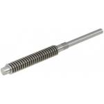
| Product name | Lead Screws For Support Units |
|---|---|
| Part number | MTSWK14-240-S70-RC-FE13-FW6-FY1 |
| Features | A dedicated lead screw configured for bearings, stopper clamp, and a position indicator |
Selection criteria
Effective as a motion transmission device to move the tale, etc.
Available sizes
■Lead screw support unit
| Lead screw | Compatible lead screw nut | |||
|---|---|---|---|---|
| Type | Material | Surface treatment | Type | Material |
| Right hand thread ・ Lent hand thread | EN 1.1191 Equiv. | - | Right hand thread ・ Lent hand thread | Brass |
| Black oxide | ||||
| Low temperature black chrome plating | ||||
| EN 1.4305 Equiv. | - | |||
■Sizes and Dimensions
| Screw shaft nominal DIA. | Pitch | Overall length | Applicable bearing | Handle mounting shaft | ||
|---|---|---|---|---|---|---|
| 1mm increment | I.D. | Width | DIA. | Length | ||
| 12 | 2 | 80 ~ 1000 | Ø8 | ≤7 | Ø6 | 2 ~ 80 |
| 14 | 3 | Ø10 | ≤8 | Ø8 | ||
| 16 | 100 ~ 1200 | Ø12 | ≤8 | Ø10 | 2 ~ 95 | |
| 18 | 4 | 150 ~ 1200 | ||||
| 20 | Ø15 | ≤9 | Ø12 | 2 ~ 100 | ||
| 22 | 5 | |||||
| 25 | ||||||
* Manufacturable ranges vary slightly depending on material, screw shaft nominal DIA. Please see the product pages for details.
Accuracy Info
■Lead screw: Screw shaft runout tolerance (Max.)
(mm)
| Screw shaft nominal | Screw shaft length | ||||||||
|---|---|---|---|---|---|---|---|---|---|
| - 125 | 126 - 200 | 201 - 315 | 316 - 400 | 401 - 500 | 501 - 630 | 631 - 800 | 801 - 1000 | 1001 - 1200 | |
| 12 | 0.09 | 0.12 | 0.16 | 0.21 | 0.27 | 0.35 | 0.46 | 0.58 | - |
| 14 | 0.09 | 0.11 | 0.13 | 0.16 | 0.2 | 0.25 | 0.32 | 0.42 | - |
| 16 | 0.09 | 0.11 | 0.13 | 0.16 | 0.2 | 0.25 | 0.32 | 0.42 | 0.55 |
| 18 - 20 | - | 0.11 | 0.13 | 0.16 | 0.2 | 0.25 | 0.32 | 0.42 | 0.55 |
| 22 - 25 | - | 0.09 | 0.11 | 0.13 | 0.16 | 0.19 | 0.23 | 0.3 | 0.38 |
■Lead screw accuracy standards
| Item | Value |
|---|---|
| Allowable dimension limit and tolerances | JISB0217 0218 |
| Screw accuracy | 7e Class |
| Nut accuracy | 7H Class |
| Single pitch error | ±0.02 |
| Cumulative pitch error | ±0.15 / 300mm |
| Length tolerance | JISB0405 (Medium class) |
| Screw shaft end DIA. tolerance | h7 |
■Shaft end DIA. tolerance
| Bearing shaft DIA. | Shaft end DIA. | Tolerance |
|---|---|---|
| Ø8 | Ø5 | +0.075 / 0 |
| Ø10 | Ø9.6 | 0 / -0.09 |
| Ø12 | Ø11.5 | 0 / -0.11 |
| Ø15 | Ø14.3 |
Technical calculations
■Lead screw・Lead screw nut selection steps
In order to verify contact surface pressure and sliding speed not to cause abnormal wear on the lead screw nut, obtain surface contact pressure P and sliding speed V.
Plot the calculated P and V values against the PV value graph and confirm the intersection.
If the intersection falls inside of line (1) and (2), it is determined that abnormal wear would not occur.
Determining of usage conditions
↓
Lead screw ・ lead screw nut temporary selection
↓
(1) Contact surface pressure P, (2)Sliding speed V calculations
Verify that the value is within (1) and (2)of the PV value graph
↓
Calculate screw efficiency η and load torque T.
(Axial load, rotational speed)
(Lead screw・lead screw nut material)
↑
(If not good)
PV Value graph
- (1) Steel (lubricated) - Brass
- (2) Steel (unlubricated) - Resin
(1) Contact surface pressure P (N/mm²)
- Fs: Shaft axial load (N)
- F0: Allowable dynamic thrust (N) → From lead screw nut specifications
Thrust when contact surface pressure of the lead screw and nut becomes 9.8 (N/mm²). - α: 9.8(Brass) 0.98(Resin)
(2) Sliding speed V (m/min)
- d2: Screw shaft effective DIA. → From lead screw specifications table
- d: Screw shaft lead angle (deg.) → From lead screw specifications table
- n: Screw shaft rotation per minute (nim-1)
(3) Screw efficiency η
- µ: dynamic friction coefficient
- d: Screw shaft lead angle (deg.)
| Screw shaft | Lead screw nut | Dynamic friction coefficient µ |
|---|---|---|
| Steel (Lubricated) | Brass | 0.21 |
| Steel (Unlubricated) | Polyacetal / sliding PPS resin | 0.13 |
(4) Load torque (N・cm)
- Fs: Shaft axial load
- η: Screw efficiency
- R: Lead (cm)

Digital Position Indicator
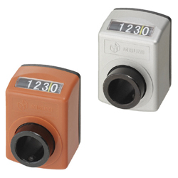
| Product name | Digital Positioning Indicators/Standard Splindle |
|---|---|
| Part number | DSNR3-CSE8 |
| Features | Compact indicators can be mounted without occupying much space. Can be selected from 4 digit or 5 digit types. |
Selection criteria
Effective as a counter mountable without taking up a large space.
Available sizes
■Compact digital position indicator (Standard, Compact type)
| Cover | Displayed digits | Rotation direction | Back plate | Sleeve | Accessory | |||
|---|---|---|---|---|---|---|---|---|
| Material | Color | Material | Material | Surface treatment | Set screw | Cushion sheet | ||
| Nylon | Orange | 4 digits ・ 5 digits | Right ・ Left | Polyphenylene ether | EN 1.0736 Equiv. | Black oxide | EN 1.7220 Equiv. | Polyethylene foam (Black) |
| Silver | 4 digits | (Black) | ||||||
■Specifications and Dimensions
| Spindle pitch | Count increment per revolution | Max. rotational speed | Applicable shaft DIA. | Reference dimension | |||
|---|---|---|---|---|---|---|---|
| 4 digits | 5 digits | (rpm) | Depth | Overall width | Overall height | ||
| 2 | 0002.0 | 00002.0 | 150 | Ø6 Ø8 Ø10 Ø12 Ø14 | (33) | 33 | 47 |
| 3 | 0003.0 | 00003.0 | 100 | ||||
| 4 | 0004.0 | 00004.0 | 75 | ||||
| 5 | 0005.0 | 00005.0 | 60 | ||||
| 6 | 0006.0 | 00006.0 | 50 | ||||


-
 Terms of use of CAD data and simplified drawing data
- These terms and conditions (hereinafter referred to as “the Terms") set forth the conditions for downloading CAD data and simplified drawing data provided by MISUMI Corporation (hereinafter referred to as "MISUMI") via www.misumi-europe.com operated by MISUMI Europa GmbH(hereinafter referred to as the "Website"). By downloading CAD data and simplified drawing data posted on the Website (hereafter referred to as “Data”), customers are deemed to have agreed to these Terms.
- 1. Purpose of Use
-
MISUMI offers the following:
1)CAD data found on the Website (3D CAD data, 3D Intermediate data and 2D CAD data) for the purpose of informing customers of the characteristics of the products offered by MISUMI or a manufacturer affiliated with MISUMI for use in their designs.
2)Simplified drawing data (in PDF format) for the purpose of checking the specifications of products. - 2. Characteristics of Data
- There may be a discrepancy in certain characteristics of products (for example: tolerance, surface roughness, chamfer, etc.) between the Data and the actual product. Furthermore, for the purpose of reducing the file size of the Data, some information such as oil groove shapes, threads, or spring shapes, may be removed from the Data.
- 3. Disclaimer
- MISUMI carefully creates the Data but makes no warranty as to the quality, accuracy, functionality, safety, reliability, etc., of the Data. MISUMI may at any time, and with no prior notice to customers, revise or delete Data. MISUMI assumes no responsibility for any damage or loss resulting from any revision or deletion of the Data, or any errors in said data. Customers are solely responsible for all aspects of their own designs, including those made using the Data. MISUMI may provide customers with design example data on the Website, but the quality, accuracy, functionality, safety, reliability, etc., of such data are not guaranteed. MISUMI may, at any time, and in its sole discretion, request that the customer cease its use of or destroy the Data in its possession. MISUMI may request the customer provide MISUMI documentation of such destruction.
- 4.Prohibited Acts
-
Customers or users of the Data, are prohibited from the following acts regarding the Data, in whole or in part:
(1)Requesting quotations or placing orders for products with third parties other than those authorized by MISUMI or its affiliates;
(2)Receiving quotations or orders for products from third parties by providing the Data to a third party or using the Data in their own business;
(3)Displaying links to the Website related to the Data on their own websites, etc., without consent of MISUMI or its affiliates;
(4)Using or reproducing the Data beyond the scope of the above-stated Purpose of Use;
(5)Modifying, altering, tampering with, translating, or adapting the Data;
(6)Selling, transferring, lending, sublicensing, or providing the Data to third parties in any way without consent of MISUMI or its affiliates;
(7)Altering the content, reverse engineering, decompiling, disassembling, or analyzing the Data;
(8)Publicly disclosing or exhibiting the Data without consent of MISUMI or its affiliates;
(9)Using the Data for the purpose of providing products and services identical or similar to those of MISUMI or its affiliates;
(10)Performing acts that interfere with the proper functioning of this Website, such as acquiring Data in bulk. - 5. Copyright
-
All title and copyright in and to any information contained in the Data are owned by MISUMI or the relevant manufacturer affiliated with MISUMI and are protected by applicable copyright laws and international treaties. By downloading Data, the customer acquires no ownership rights of any kind in the intellectual property contained within. Without prior approval from MISUMI, no part of the Data may be utilized (reproduced, modified, reverse-engineered, uploaded, presented, sent, distributed, licensed, sold, or published) for any purpose other than that mentioned above.
In the event Data is found to have been to be used for any purpose other than that mentioned above or against any applicable laws or the Terms, MISUMI may pursue any legal remedy available to it, which may result in forbidding the offending user from using the Data or accessing the Website. - 6. Third-Party Data
- MISUMI offers some Data provided by third parties. Such Data may be subject to separate terms and conditions, in addition to these terms. MISUMI makes no guarantee or warranty regarding Data from third parties.
- 7. Export Control
- Customers shall comply with all applicable laws and regulations regarding the export of the Data.
- 8. Amendments to the Terms
- MISUMI may, at any time, and in its sole discretion, modify these terms and conditions; any such modification will be effective immediately.
- 9. Severability
- If any term or provision of these Terms is invalid, illegal, or unenforceable in any jurisdiction, such invalidity, illegality, or unenforceability shall not affect any other term or provision of these Terms or invalidate or render unenforceable such term or provision in any other jurisdiction. Section 139 BGB (German Civil Code) shall not apply.
- 10.Miscellaneous
-
In the event that Customers violate the Terms, MISUMI and/or MISUMI Europa GmbH shall be entitled to claim the damages and expenses (including attorney's fees) incurred by such violation against the Customers.
These Terms and any disputes arising in connection therewith shall be exclusively governed by and construed in accordance with the laws of the Federal Republic of Germany, without regard to its conflicts of law principles. The courts located in Frankfurt am Main/Germany shall have exclusive jurisdiction to adjudicate any dispute arising in connection with these Terms. By downloading the Data, you agree to submit to the exclusive and personal jurisdiction of the courts located in Frankfurt am Main/Germany. - Revised: September 21, 2025
CAD Data Download (Unit Assembly)
CAD Data Download: File Format
Cautions on the CAD data
-
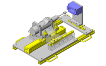
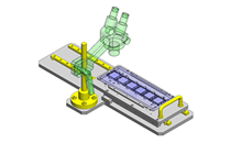
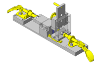
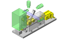
Assembly data shows the assembly drawings in the concept design phase. The sole purpose of the data is to explain the structure and functionality of the assembly and is not considered nor to be used as a final design.
You will need to edit the Data so that it meets your specific design conditions. -
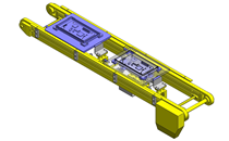
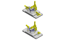
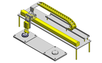
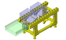
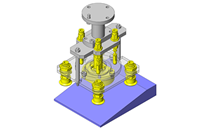
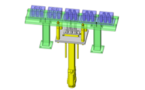
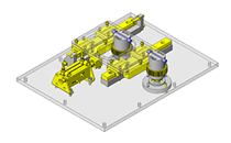
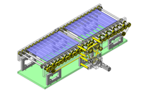
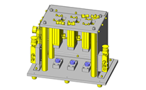
The CAD data unit assembly consists of sub-assemblies.
Each sub-assembly unit can be used as it is or can be edited. - The Data for fabricated parts is based on easy-to-edit dimensions and shapes in sketches and histories.
- The Data including the third-part components are made by the Company.
* The part in the frame is a sub-assembly unit.
-

- * Unit assembly CAD data consists of some sub-assemblies.
Each sub-assembly unit can be used as it is or can be edited.
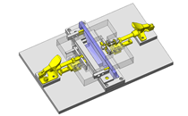
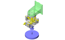
Application Overview
Purpose
- Purpose
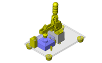
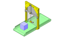
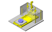
- Adjust workpiece height during engraving process.
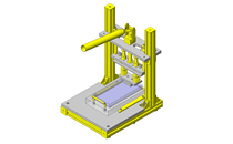
- Operation
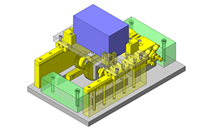
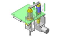
- First loosen the lead screw by unlocking the lead screw clamp mounted behind the position indicator. Adjust the height of the workpiece by rotating the hand crank wheel at the end. A vertical scale is mounted beside the lead screw support to provide height adjustments, lock the lead screw clamp again to maintain position.
Points for use
- Secure and maintain height positions.
Target workpiece
- Shape: Name plate
- Size: W50 x D100 x H2mm
- Weight 40g
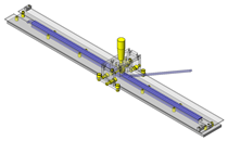
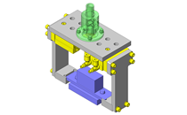
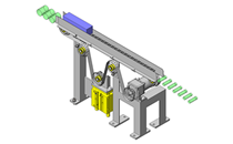
Design Specifications
Operating Conditions or Design Requirements
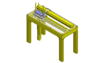
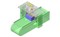
- Elevator stroke: ±10mm
- Distance from the sensor flag to overload detection sensor: 4.37mm
- External size: W510 x D380 x H157mm
Required Performance
- Positioning accuracy: ±0.1mm
- Load weight: 25kg
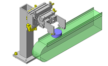
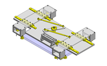
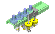
Selection Criteria for Main Components
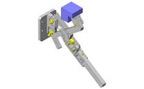
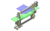
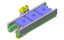
- The linear guide incline angle 18° set as diagonally mounted wedge, a lead screw with 3mm lead is selected in order to obtain 1mm elevation per 1 rotation of the handle (tan18° x 3 ≈ 1).
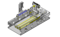
Design Evaluation
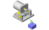
Verification of main components
- Verify the manual operation force against the moving body.
- Confirmation of the force to rotate the handle.
- Conditional value: Moving body mass W = 25kg, Gravitational acceleration g = 9.8m/s², Lead screw lead
R = 3mm = 0.3cm, lead angle d = 4° 22' = 4.37°, dynamic friction coefficient µ = 0.21, linear guide incline angle θ = 18°, Lever position from the center of handle L = 22mm = 2.2cm - Force acting in the vertical direction: W = m x g = 25 x 9.8=245N
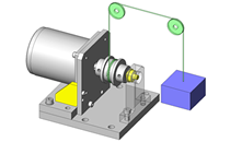
- Force acting in the horizintal direction: F = W x tanθ = 245 x tan18° = 79.6N
- Screw efficiency: η = (1 - µ x tan (d)) / (1 + µ / tan (d)) = (1 -0.21 x tan4.37°) / (1 + 0.21 / tan4.37°) = 0.263
- Load torque: T = (F x R) / (2 x π x η) = (79.6 x 0.3) / (2 x π x 0.263) = 14.5N・cm
Force applicable on lever of the handle P = T / L = 14.5 / 2.2 = 6.6N
- Conditional value: Moving body mass W = 25kg, Gravitational acceleration g = 9.8m/s², Lead screw lead
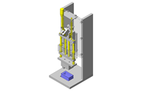
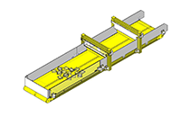
Other Design Consideration
- The rotary to lifting mechanism is made possible by the use of lead screw and an angle mounted linear slide.
- The height of the workpiece is fixed by locking the lead screw using a clamp.
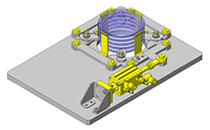
- A vertical scale is mounted to provide height readout.
Explore Similar Application Examples


Payment Method


On-Demand Manufacturing
Certificates


Copyright © MISUMI Corporation All Rights Reserved.