
- inCAD Library Home
- > No.000281 Centering mechanism
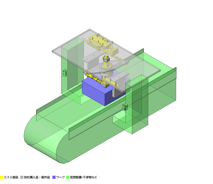
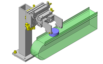
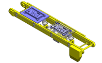
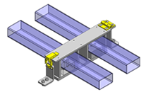
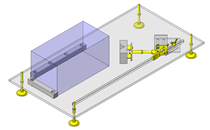
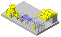
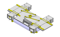
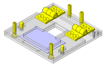
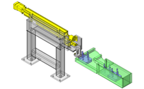
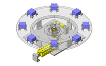
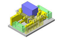
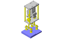
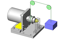
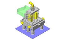
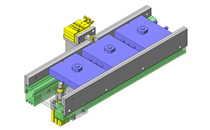
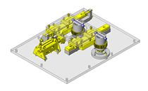
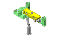
No.000281 Centering mechanism
18
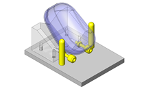
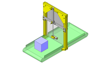
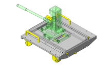
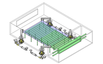
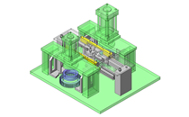
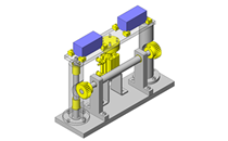
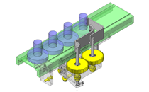
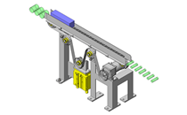
A single cylinder centering mechanism
Related Category


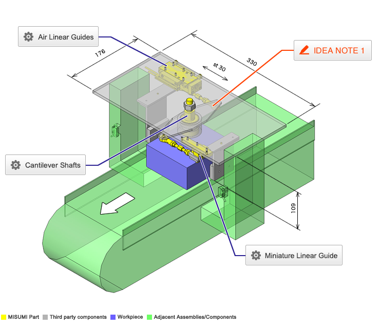
Cantilever Shafts
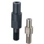
| Product name | Cantilever Shafts/Pilot/Standard/Threaded/w Tapped End |
|---|---|
| Part number | SFXCB15-18-F29-G6-MA8 |
Selection criteria
Select the standard item to use as the fulcrum of the link rotation
Available sizes
■Cantilever Shafts - Pilot Type - Standard, Threaded, with Tapped End
| Material | Surface Treatment |
|---|---|
| EN 1.1191 Equiv. | Black Oxide |
| Electroless Nickel Plating | |
| EN 1.4301 Equiv. | - |
■Sizes and Dimensions
| Pin Dia. (mm) | (1 mm Increments) | M(Coarse) | |||
|---|---|---|---|---|---|
| Y | F | G | N | ||
| 6 | 2-60 | 5-100 | 5-10 | 6-12 | M6 |
| 8 | 8-16 | M8 | |||
| 10 | 10-20 | M10 | |||
| 12 | 10-150 | 5-15 | 12-24 | M12 | |
| 13 | |||||
| 15 | |||||
| 16 | |||||
| 17 | 5-20 | ||||
| 18 | |||||
| 20 | 4-75 | 20-40 | M20 | ||
| M16 | |||||
| 22 | M20 | ||||
| M16 | |||||
| 25 | M20 | ||||
| M16 | |||||
| 30 | M20 | ||||
| M16 | |||||
Accuracy Info
■Accuracy of Cantilever Shafts
Perpendicularity: 0.02
| Pin Dia. (mm) | Tolerance g6 (mm) |
|---|---|
| 6 | -0.004 -0.012 |
| 8 | -0.005 -0.014 |
| 10 | |
| 12 | -0.006 -0.017 |
| 13 | |
| 15 | |
| 16 | |
| 17 | |
| 18 | |
| 20 | -0.007 -0.020 |
| 22 | |
| 25 | |
| 30 |

Miniature Linear Guide
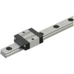
| Product name | Miniature Linear Guides/Short Block |
|---|---|
| Part number | SSEBSZ13L-70 |
| Features | 20% more compact than standard blocks. |
Selection criteria
Select a linear guide to obtain the accurate motion of claws.
Available sizes
■Miniature Linear Guide - Short Block
| Material | Hardness |
|---|---|
| Stainless Steel | 56 HRC or more |
| Free Cutting Steel (Alloy Steel including SCM) | 58 HRC or More |
■Sizes and Dimensions
| Overall Height | Block Width | Block Length | Rail Length |
|---|---|---|---|
| 8 | 17 | 19.6 | 40 ~ 130 |
| 10 | 20 | 22.9 | 35 ~ 275 |
| 13 | 27 | 27 | 45 ~ 470 |
| 16 | 32 | 32.7 | 70 ~ 670 |
Selection steps
■Miniature Linear Guide Selection Steps
- Determine conditions of use
- (Moving mass, feed rate, motion pattern, life)
↓
- Temporary select linear guide specifications
- (Block type, overall height, rail length are temporarily selected
according to the conditions of use.)
↓
- Basic safety check
-
- ●Allowable Load
- ●Operating Life
- ●Preload
Accuracy Info
■Preload and Accuracy Standards (Normal Preload, Slight Clearance type)
Light Preload, Slight Clearance Type
| Light Preload High Grade | Slight Clearance Standard Grade | |
|---|---|---|
| Radial Clearance | -3 ~ 0 | 0 ~ +15 |
| Dimensional Accuracy(μm) | High Grade | Standard Grade | |
|---|---|---|---|
| H Dimension Tolerance | ±20 | ±20 | |
| Pair Variation of H | 15 | 40 | |
| W2 Dimension Tolerance | ±25 | ±25 | |
| Pair Variation of H | 20 | 40 | |
■Running Parallelism
(μm)
| Rail Length(mm) | ||||||||||
|---|---|---|---|---|---|---|---|---|---|---|
| ~ 50 | 51 ~ 80 | 81 ~ 125 | 126 ~ 200 | 201 ~ 250 | 251 ~ 315 | 316 ~ 400 | 401 ~ 500 | 501 ~ 630 | 631 ~ 800 | |
| High Grade | 3 | 3 | 7 | 7 | 9 | 11 | 11 | 12 | 13.5 | 14 |
| Standard Grade | 13 | 13 | 15 | 15 | 17 | 18 | 18 | 19 | 21 | 21.5 |
* The slight clearance type has clearances (play) between the rails and blocks.
Performance info.
■Load Rating of Miniature Linear Guides (Short Blocks, Light Preload / Slight Clearance Type)
| Overall Height | Basic Load Rating | Allowable Static Moment | |||
|---|---|---|---|---|---|
| C (Dynamic) kN | Co (Static) kN | MA N ・ m | MB N ・ m | Mc N ・ m | |
| 8 | 0.79 | 1.27 | 1.9 | 1.6 | 4.6 |
| 10 | 1.16 | 1.68 | 3.1 | 2.6 | 7.9 |
| 13 | 1.63 | 2.38 | 5.2 | 4.4 | 14.8 |
| 16 | 3.08 | 4.23 | 12.3 | 10.3 | 32.6 |
Technical calculations
■Operating Life Calculation for Linear Guides
- ●Operating Life
- When the linear guide is loaded in linear reciprocating motion, scaly damages called flaking appear due to material fatigue as the stress works on the rolling elements (steel balls) and the rolling contact surfaces (rails) constantly. Total travel distance until the first flaking occurs is called the life of linear guides.
- ●Rated Life
- Rated life is the total travel distance that 90% of linear guides of the same type can reach, under the same conditions, with no occurrence of flaking damage. Rated life can be calculated with the basic dynamic load rating and the actual load applied on the linear guides, as shown below.
-
- Load must be calculated before actually using linear guides. To obtain loads during linear reciprocating motion, it is necessary to fully consider vibrations and impacts during motion as well as distribution condition of the load applied to linear guides. So, it is not easy to calculation the loads. Operating temperature also critically affects the life. Considering these conditions, the above-mentioned calculation formula will be as follows.
-
- L: Rated Life (Km)
- fH: Hardness Factor (See Fig.1)
- fT: Temperature Factor (See Fig.2)
- fC: Contact Factor (See Table-1)
- fW: Load Factor (See Table-2)
- C: Basic Dynamic Load Rating (N)
- P: Applied Load (N)
- ●Hardness Factor (fH)
-
For linear applications, the shafts and ball bearings must have sufficient hardness. If they do not, the load rating decreases and the life will be reduced.
Please correct the rated life with the hardness factor.
- ●Temperature Factor (fT)
-
When the temperature of the linear system exceeds 100 degrees C, the hardness will decrease and as a result, the allowable load and life will reduced.
* Please use Linear Guides at within the heat resistance temperature ranges shown on product pages.
- ●Contact Factor (fC)
-
Table-1. Contact Factor
Number of Blocks per Rail Contact Factor fC
1 1.00 2 0.81 3 0.72 4 0.66 5 0.61 For actual applications, more than two blocks are generally used per shaft. In this case, the load applied to each block varies depending on machining precision and is not uniformly distributed. As a result, per-linear guide allowable load varies depending on the number of linear guides per rail.
Please compensate rated life with Contact Factors on Table - 1.
- ●Load Factor (fW)
-
Table-2. Load Factor
Condition of Use fw No external shocks / vibrations,
low speed 15 m/min or less1.0-1.5 No significant shocks / vibrations,
medium speed 60 m/min or less1.5-20 With external shocks / vibrations,
high speed exceeding 60 m/min2.0-3.5 To calculate load applied to the Linear Guides, in addition to object weight, it requires inertia force attributed to motion velocity or moment loads. However, it is difficult to calculation the load accurately due to potential vibrations and shocks caused by other element than repeated start-stop motions during reciprocating motion.
Thus, table-2 load factor helps simplify the life calculation.
- ●Applied Load P Calculation Method
- When moment load is applied to each block, convert the moment load into applied load by the following formula.
-

- P: Applied Load (N)
- F: Downward load (N)
- Co: Static Load Rating (N)
- MA: Allowable Static Moment - Pitching Direction (N・m)
- MC: Allowable Static Moment - Rolling Direction (N・m)
- Lp: Load Point Distance (m) in Pitching Direction
- Lr: Load Point Distance (m) in Rolling Direction

Air Linear Guides
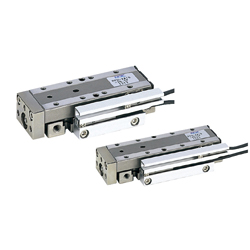
| Product name | Air Linear Guides/MPPU10 Series |
|---|---|
| Part number | MPPU10-30-SMT |
Selection criteria
Select a drive source with guides to omit the linear motion guide of one side.
Available sizes
■Air Linear Guides - MPPU10 Series
| Cyl. Bore | Horizontal (mm) | Vertical (mm) | Thickness (mm) | Stroke Length (mm) |
|---|---|---|---|---|
| Ø10 | 27 | 70 | 20 | 15 |
| 85 | 30 | |||
| 100 | 45 | |||
| Ø12 | 32 | 76 | 22 | 20 |
| 86 | 30 | |||
| 101 | 45 | |||
| 116 | 60 |
Accuracy Info
| Bore Dia. | Ø10 | Ø12 | ||
|---|---|---|---|---|
| Stroke | 15/30/45 | 20/30/45 | 60 | |
| Parallelism | Plane C to Plane A | 0.02 | 0.02 | |
| Plane D to Plane B | 0.02 | 0.02 | ||
| Running Parallelism | Plane C to Plane A | 0.004 | 0.004 | 0.006 |
| Plane D to Plane B | 0.004 | 0.004 | 0.006 | |
| Perpendicularity | Plane E to Plane A | 0.15 | 0.15 | |
| Plane E to Plane B | 0.15 | 0.15 | ||
| J Dimension Tolerance | ±0.025 | ±0.025 | ||
| F Dimension Tolerance | ±0.2 | ±0.2 | ||
| G Dimension Tolerance | ±0.2 | ±0.2 | ||
| H Dimension Tolerance | ±0.05 | ±0.05 | ||
Performance info.
■Speeds / Loads (Load Info.) of Air Linear Guides
■Operating Pressure Range
Min. Operating Pressure (MPa): 0.15
Max. Operating Pressure (MPa): 0.70
Pressure Resistance (Mpa): 1.05
■Theoretical Thrust
Unit: N
| Cyl. Bore | Operation Direction | Rod Dia. (mm) | Operating Pressure (MPa) | |
|---|---|---|---|---|
| 0.4 | 0.5 | |||
| Ø10 | Outstroke | Ø4 | 31 | 39 |
| Instroke | 26 | 33 | ||
| Ø12 | Outstroke | Ø5 | 45 | 57 |
| Instroke | 37 | 47 | ||
■Basic Static Load Ratings / Allowable Static Moments
| Cyl. Bore | Stroke (mm) | Basic Static Load Rating Co(kN) | Allowable Load Moment N・m | ||
|---|---|---|---|---|---|
| Pitching | Yawing | Rolling | |||
| Ø10 | 15/30/45 | 3.4 | 20.5 | 24.5 | 22.5 |
| Ø12 | 20/30/45/60 | 4.9 | 32.3 | 38.2 | 41.1 |


-
 Terms of use of CAD data and simplified drawing data
- These terms and conditions (hereinafter referred to as “the Terms") set forth the conditions for downloading CAD data and simplified drawing data provided by MISUMI Corporation (hereinafter referred to as "MISUMI") via www.misumi-europe.com operated by MISUMI Europa GmbH(hereinafter referred to as the "Website"). By downloading CAD data and simplified drawing data posted on the Website (hereafter referred to as “Data”), customers are deemed to have agreed to these Terms.
- 1. Purpose of Use
-
MISUMI offers the following:
1)CAD data found on the Website (3D CAD data, 3D Intermediate data and 2D CAD data) for the purpose of informing customers of the characteristics of the products offered by MISUMI or a manufacturer affiliated with MISUMI for use in their designs.
2)Simplified drawing data (in PDF format) for the purpose of checking the specifications of products. - 2. Characteristics of Data
- There may be a discrepancy in certain characteristics of products (for example: tolerance, surface roughness, chamfer, etc.) between the Data and the actual product. Furthermore, for the purpose of reducing the file size of the Data, some information such as oil groove shapes, threads, or spring shapes, may be removed from the Data.
- 3. Disclaimer
- MISUMI carefully creates the Data but makes no warranty as to the quality, accuracy, functionality, safety, reliability, etc., of the Data. MISUMI may at any time, and with no prior notice to customers, revise or delete Data. MISUMI assumes no responsibility for any damage or loss resulting from any revision or deletion of the Data, or any errors in said data. Customers are solely responsible for all aspects of their own designs, including those made using the Data. MISUMI may provide customers with design example data on the Website, but the quality, accuracy, functionality, safety, reliability, etc., of such data are not guaranteed. MISUMI may, at any time, and in its sole discretion, request that the customer cease its use of or destroy the Data in its possession. MISUMI may request the customer provide MISUMI documentation of such destruction.
- 4.Prohibited Acts
-
Customers or users of the Data, are prohibited from the following acts regarding the Data, in whole or in part:
(1)Requesting quotations or placing orders for products with third parties other than those authorized by MISUMI or its affiliates;
(2)Receiving quotations or orders for products from third parties by providing the Data to a third party or using the Data in their own business;
(3)Displaying links to the Website related to the Data on their own websites, etc., without consent of MISUMI or its affiliates;
(4)Using or reproducing the Data beyond the scope of the above-stated Purpose of Use;
(5)Modifying, altering, tampering with, translating, or adapting the Data;
(6)Selling, transferring, lending, sublicensing, or providing the Data to third parties in any way without consent of MISUMI or its affiliates;
(7)Altering the content, reverse engineering, decompiling, disassembling, or analyzing the Data;
(8)Publicly disclosing or exhibiting the Data without consent of MISUMI or its affiliates;
(9)Using the Data for the purpose of providing products and services identical or similar to those of MISUMI or its affiliates;
(10)Performing acts that interfere with the proper functioning of this Website, such as acquiring Data in bulk. - 5. Copyright
-
All title and copyright in and to any information contained in the Data are owned by MISUMI or the relevant manufacturer affiliated with MISUMI and are protected by applicable copyright laws and international treaties. By downloading Data, the customer acquires no ownership rights of any kind in the intellectual property contained within. Without prior approval from MISUMI, no part of the Data may be utilized (reproduced, modified, reverse-engineered, uploaded, presented, sent, distributed, licensed, sold, or published) for any purpose other than that mentioned above.
In the event Data is found to have been to be used for any purpose other than that mentioned above or against any applicable laws or the Terms, MISUMI may pursue any legal remedy available to it, which may result in forbidding the offending user from using the Data or accessing the Website. - 6. Third-Party Data
- MISUMI offers some Data provided by third parties. Such Data may be subject to separate terms and conditions, in addition to these terms. MISUMI makes no guarantee or warranty regarding Data from third parties.
- 7. Export Control
- Customers shall comply with all applicable laws and regulations regarding the export of the Data.
- 8. Amendments to the Terms
- MISUMI may, at any time, and in its sole discretion, modify these terms and conditions; any such modification will be effective immediately.
- 9. Severability
- If any term or provision of these Terms is invalid, illegal, or unenforceable in any jurisdiction, such invalidity, illegality, or unenforceability shall not affect any other term or provision of these Terms or invalidate or render unenforceable such term or provision in any other jurisdiction. Section 139 BGB (German Civil Code) shall not apply.
- 10.Miscellaneous
-
In the event that Customers violate the Terms, MISUMI and/or MISUMI Europa GmbH shall be entitled to claim the damages and expenses (including attorney's fees) incurred by such violation against the Customers.
These Terms and any disputes arising in connection therewith shall be exclusively governed by and construed in accordance with the laws of the Federal Republic of Germany, without regard to its conflicts of law principles. The courts located in Frankfurt am Main/Germany shall have exclusive jurisdiction to adjudicate any dispute arising in connection with these Terms. By downloading the Data, you agree to submit to the exclusive and personal jurisdiction of the courts located in Frankfurt am Main/Germany. - Revised: September 21, 2025
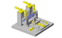
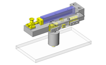
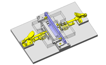
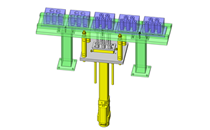
CAD Data Download (Unit Assembly)
CAD Data Download: File Format
Cautions on the CAD data
-
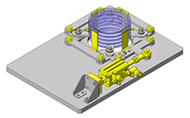
Assembly data shows the assembly drawings in the concept design phase. The sole purpose of the data is to explain the structure and functionality of the assembly and is not considered nor to be used as a final design.
You will need to edit the Data so that it meets your specific design conditions. -
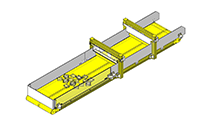
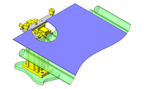
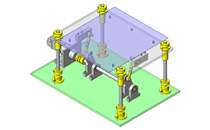
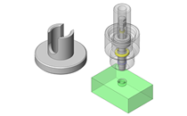
The CAD data unit assembly consists of sub-assemblies.
Each sub-assembly unit can be used as it is or can be edited. - The Data for fabricated parts is based on easy-to-edit dimensions and shapes in sketches and histories.
- The Data including the third-part components are made by the Company.
* The part in the frame is a sub-assembly unit.
-

- * Unit assembly CAD data consists of some sub-assemblies.
Each sub-assembly unit can be used as it is or can be edited.
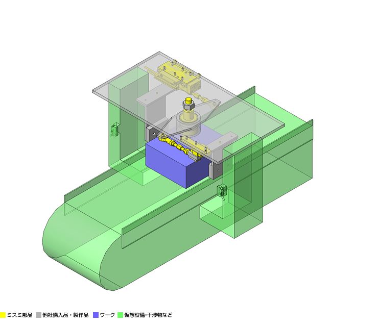
Application Overview
Purpose
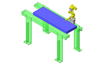
- Operation
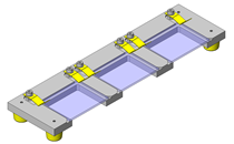
(1) A workpiece transferred by the conveyor is stopped by the sensor.
(2) The cylinder conducts synchronous centering.
(3) The workpiece is adjusted.
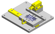
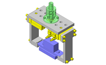
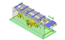
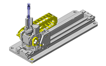
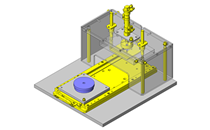
Points for use
- Automatic operation by means of an air cylinder
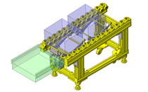
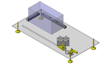
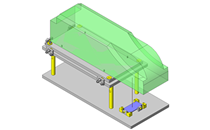
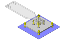
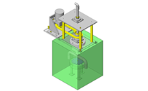
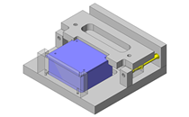
Target workpiece
- Plastic boxes
- External dimensions: W120 x D106 x H50mm
- Workpiece weight: 1kg
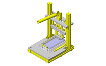
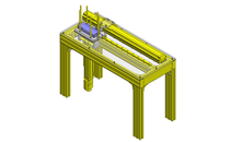
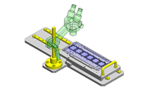
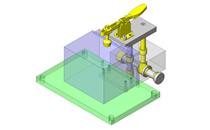
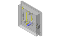
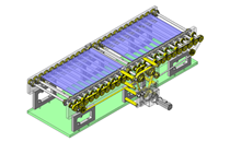
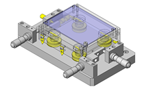
Design Specifications
Operating Conditions or Design Requirements
- External dimensions: W176 x D330 x H109mm
- Cylinder stroke: 30mm
- Conveyor speed: 70mm/s
Required Performance
- Assumed outstroke force: 15N
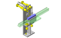
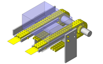
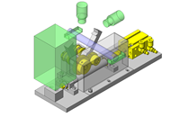
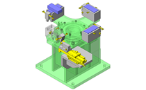
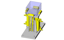
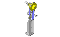
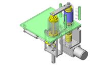
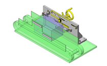
Selection Criteria for Main Components
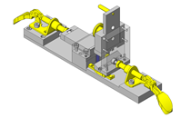
- Cylinder attached with a guide
- Select one that can conduct workpiece centering.
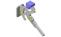
- Linear guides
- Select a guide that is suited for the claw size because the moment load is not large.
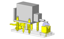
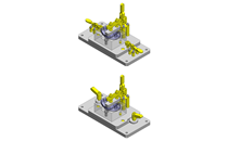
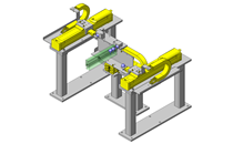
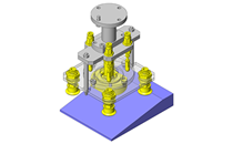
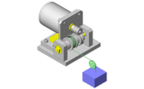
Design Evaluation
Verification of main components
- Verify the cylinder thrust for adequate workpiece centering force.
- Cylinder
- Conditional values: Workpiece weight F1 = 10N, part pushed and pulled by the cylinder F2 = 6N, shaft dia. d = 12mm, friction coefficient workpiece vs. conveyor μ1 = 0.8, friction coefficient of linear guides μ2 = 0.1, the shortest distance between shaft and cylinder L = 70mm, load factor = 0.5, operating pressure = 0.4MPa, tube inner dia. cross sectional area = π/4 x 102mm²
- Let the force to conduct workpiece centering be P [N]. Then, we have {(F1 x μ1) + (F2 x μ2)} x (d/2) = L x P . Thus, (10 x 0.8 + 6 x 0.1) x 6 = 70 x P → P = 0.74N
- Cylinder thrust = Load factor x Operating pressure x Tube inner dia. cross sectional area = 0.5 x 0.4MPa x π/4 x 102mm² = 15.7N > 0.74N
⇒No problem.
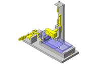
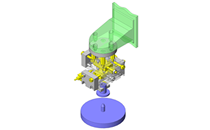
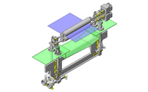
Other Design Consideration
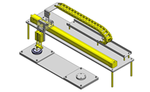
- The workpiece centering position can be adjusted with the rod-end bearing. Furthermore, workpieces with different sizes can be handled because of sufficient room for screw adjustment.
- Has a compact structure because of the integration of the linear guides and air cylinder.
Explore Similar Application Examples


Payment Method


On-Demand Manufacturing
Certificates


Copyright © MISUMI Corporation All Rights Reserved.